 Simon Prickett

Having written guides describing how to use the Low Voltage Labs traffic lights with the Raspberry Pi for Python (read Python article), Swift (read Swift article), Node.js (read Node.js article), Node RED (read Node RED article), Java (read Java article), Bash scripting (read Bash article), Go (read Go article), .NET/C#, Rust and Arduino, I figured it must be time to take a look at how to access the GPIO pins from the C programming language.
To make this a standalone guide, there will be some re-use of content from the prior articles here.
Shopping List
To try this out, you will need the following (links here mostly go to Adafruit, UK customers may want to consider Pimoroni as a UK based alternative, Amazon has most if not all of this stuff too):
- A Raspberry Pi (I’ll use the Pi 3 Model B here, but any model with GPIO pins will work — if you want to use the Pi Zero you’ll need to solder some headers onto it). I’m going to assume you have a Pi 2 or 3 with 40 pins
- A power supply for your Pi (Raspberry Pi 4 requires a different USB C power supply)
- Some sort of case is probably a good idea to protect the Pi (but you’ll need to leave the lid off to expose the GPIO pins to connect your lights to)
- A Micro SD card to install your operating system on (or get one with the OS pre-installed). If you want to install the operating system yourself, you’ll need a Mac, PC, Linux machine with an SD card reader
- A set of traffic lights from Low Voltage Labs (the two pack is good value)
- Any USB keyboard to type on the Pi, you might want a mouse too
- Any HDMI display to show output from the Pi
Attaching the Traffic Lights
The Low Voltage Labs traffic lights connect to the Pi using four pins. One of these needs to be ground, the other three being actual GPIO pins used to control each of the individual LEDs.

Before powering up the Pi, attach the traffic lights so that the pins connect to the GPIO pins highlighted in red:
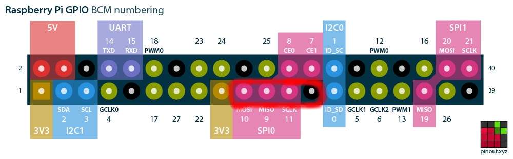
When you’re done it’s going to look something like this… (an easy way to make sure you have it right is to locate the lights on the left hand row of pins as you look at the Pi with the USB ports to the bottom, then count 8 pins up and attach the lights there).


Don’t turn the Pi on yet, you’ll need to prepare an operating system image for it first…
Operating System Setup
Install the Raspberry Pi OS which can be downloaded from the official Raspberry Pi site. You can also find an excellent installation guide there should you need help.
Once you’ve got the operating system installed, make sure you can login, and have a working wired or wifi internet connection.
Your support helps to fund future projects!
Now you can go ahead and start turning lights on and off!
Installing Dependencies
We’ll need a couple of tools to turn our C source code into a binary executable. Let’s verify that we have gcc (C compiler) and make (build automation tool) installed:
$ gcc --version
gcc (Raspbian 6.3.0-18+rpi1+deb9u1) 6.3.0 20170516
Copyright (C) 2016 Free Software Foundation, Inc.
This is free software; see the source for copying conditions.  There is NO warranty; not even for MERCHANTABILITY or FITNESS FOR A PARTICULAR PURPOSE.
$ make --version
GNU Make 4.1
Built for arm-unknown-linux-gnueabihf
Copyright (C) 1988-2014 Free Software Foundation, Inc.
License GPLv3+: GNU GPL version 3 or later <http://gnu.org/licenses/gpl.html>
This is free software: you are free to change and redistribute it. There is NO WARRANTY, to the extent permitted by law.
Those come with the operating system image, so no installation required. We will however need to install git so we can download the sample code from GitHub:
$ sudo apt-get install git
$ git --version

git version 2.11.0
Downloading the Sample Code
I’ve written some sample C code to demonstrate running the traffic lights in the UK light sequence (red, red + amber, green, amber, red):

To get the source code for this example from GitHub:
$ git clone https://github.com/simonprickett/cpitrafficlights.git
For convenience, set an environment variable to contain the path to the source code repo:
$ cd cpitrafficlights
$ PROJECTDIR=`pwd`
We’ll use that later…
C Programming with WiringPi
WiringPi is a mature and well tested library for working with GPIO pins on the Raspberry Pi from C. Using this allows us to get straight down to the business of controlling the lights without having to worry about lower level concerns.
Installing WiringPi
WiringPi isn’t installed with the “lite” Raspberr Pi OS operating system, but it’s easy to fix that:
$ git clone git://git.drogon.net/wiringPi
$ cd wiringPi
$ ./build
Compiling and Running the Demo
Next, let’s compile the demo code that we downloaded from GitHub and make sure it works…
$ cd $PROJECTDIR/cpitrafficlights/wiringpi
$ make
$ ./trafficlights
If the lights are connected to the correct GPIO pins, they should start to flash on and off. If you don’t see anything, make sure that you have the lights connected to the right pins. To exit, press Ctrl + C. This will cause all of the lights to turn off, and the program will terminate.
How it Works
Here’s the code, contained in trafficlights.c in the GitHub repo:
Lines 1–4 pull in the header files for the WiringPi library, plus some other functionality we’ll need — signal.h and stdlib.h provide functions that we will be use to tidy up and quit nicely when the user presses Ctrl+C, stdio.h allows us to output status to the terminal via standard out.
Lines 6–8 provide convenient names for the GPIO pins that control each light. Note that WiringPi uses a different pin numbering scheme, so GPIO 9 (Red) becomes pin 13 for example. This mapping diagram shows the WiringPi pin numbers and their corresponding BCM mode pin numbers that are used in my other Pi Traffic Light articles for other programming languages.
Lines 13–17 define a convenience function that will turn all of the lights off using WiringPi’s digitalWrite function to set each pin that a light is connected to LOW (defined by WiringPi).
Lines 19–22 define a function that will be invoked when the user wants to quit the program and presses Ctrl + C… this will turn all of the lights off and exit back to the shell.
Lines 24–64 are the entry point / main function, which first registers the function defined at 19–22 as a handler for SIGINT (Ctrl + C), trapping and handling that signal to ensure that we exit cleanly and turn the lights off on the way out. Lines 27–30 initialize the WiringPi library, and lines 32–34 configure each of the GPIO pins we’re using as outputs. pinMode is a function provided by WiringPi, as is the OUTPUT constant.
We then turn all the lights off at line 36 ensuring we’re in a known state when we start. The code enters an infinite while loop, in which it uses WiringPi’s digitalWrite function to turn individual lights on — HIGH or off LOW (constants provided by WiringPi). It also uses the delay function provided by WiringPi to wait a few seconds before changing the state of the lights. Having cycled through the red, red / yellow, green, yellow states the loop starts again and continues indefinitely until the user presses Ctrl + C to invoke the SIGINT signal handler.
The source code for this project is freely available on GitHub.
I’d love to hear what you’re up to with the Raspberry Pi — get in touch via the Contact page. If you enjoyed this article, please share it far and wide!
 Raspberry Pi Coding with Node.js: Traffic Lights