 Simon Prickett

Node RED is a tool that has interested me for some time - specifically when used on the Raspberry Pi to control or receive input from hardware devices. As part of my series of posts demonstrating how to control GPIO pins on the Raspberry Pi using the excellent Low Voltage Labs traffic lights, I decided to check out how to do this with Node RED.
If you’re interested in controlling the same traffic lights from different programming environments, check out my other articles:
I’ve also been meaning to write this post for some time, as I made a video version of it over a year ago then never followed up with the blog version. I’ve been taking part in a few Homebrew Website Club in person meetings in San Diego, and found those really helpful for providing structured time to work on website stuff with like minded people. Today I attended a virtual “Get On With It! Bring Your Own Project” meetup organized by Ladies of Code London, and committed to writing this post today as part of that. The event provided a sense of getting things done together even while remote, with Slack and Zoom check ins during a defined working period. Everyone was very friendly and I’ll definitely try to attend more of these. I wasn’t able to spend much of the actual period working on this post due to the time zone difference to the rest of the group who were mostly in the UK, but it got me started and I spent time later in my day finishing up!
Node RED is a “low code” programming environment for event driven applications. Rather than writing all of your logic in a series of source files before running them through a compiler or interpreter, you build a Node RED application as a flowchart of connected “nodes”. Built on top of the Node.js runtime, Node RED provides a graphical environment to build these flows in the browser. Some nodes in the flow have a fixed purpose, others can be configured using property forms, and you can also write regular JavaScript / Node.js logic to implement a node’s behavior. Nodes pass data between them as JSON messages.
Your support helps to fund future projects!
You can use Node RED on a regular computer, but I wanted to try it on the Raspberry Pi to see what it offers for developing applications that use the Pi’s GPIO pins.
Project Overview
As usual, I decided to use the traffic light LEDs that I had on hand and model the UK traffic light pattern with them. For those not familiar with that, in the UK a traffic light cycles like this (see the Highway Code):
- Start
- Red only: Stop!
- Red and yellow (amber): Stop! (but the light is about to change to…)
- Green only: Proceed with caution if the way is clear!
- Yellow (amber): Complete your turn if you already passed the stop line, but don’t cross the stop line if you haven’t already done so.
- Go to Start
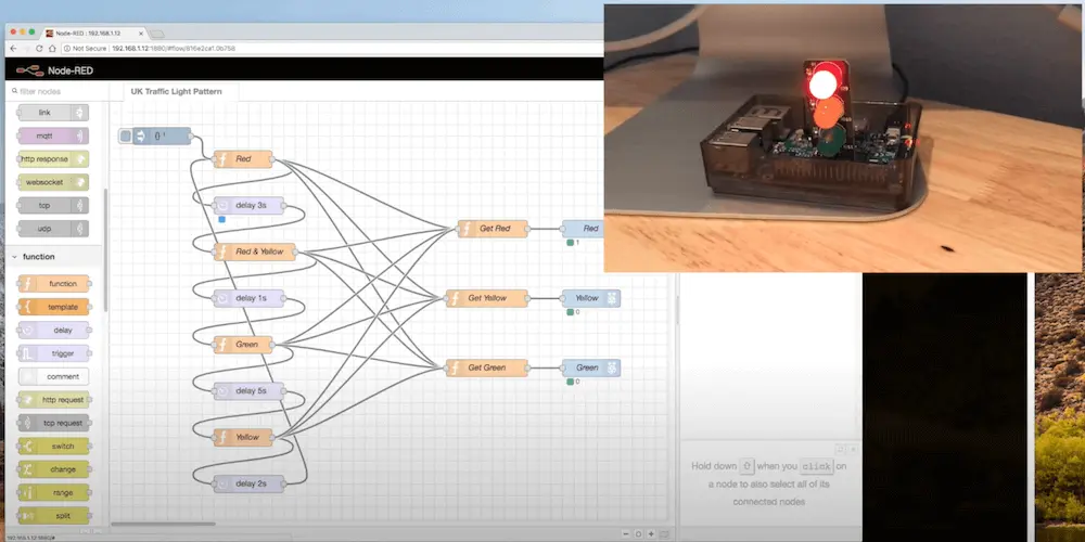
We’ll need to remember this set of states for later, but here’s a GIF of what they will look like when we’re finished:
My aim was to see if I could quickly go from no experience to a working traffic light sequence. If you’d prefer to see how to do this as a video tutorial, I made one as I went along…
Getting Started
I used a Raspberry Pi 3 with the Raspberry Pi OS lite operating system as I didn’t need a graphical desktop environment. The traffic lights attach to four of the Pi’s GPIO pins. One of these has to be a ground pin, the other three are used to control each of the three LED lights. I attached mine to GPIO pins 9, 10, 11. I also connected the Pi to my wireless network then installed an up to date version of Node.js on it.
If you’d like to see how to set up the operating system on the Pi and connect the lights to the GPIO pins, check out my earlier article which has a complete walkthrough for this.
Before we can use Node RED, we obviously need to install it! Once connected to the Pi with SSH, Node RED is installed using npm:
$ sudo npm install -g --unsafe-perm node-redThis will install Node RED globally and might take a little while. We can then start it up:
$ node-redNode RED starts up on port 1880, and its graphical environment can be accessed from a browser at:
http://<IP Address of Raspberry Pi>:1880/Where <IP Address of Raspberry Pi> is the Pi’s IP address that you used to SSH into it when installing Node RED. We’re now ready to start building a flow!
Building a Traffic Light Flow
When you first start Node RED, you’ll see a blank flow workspace which looks like this:
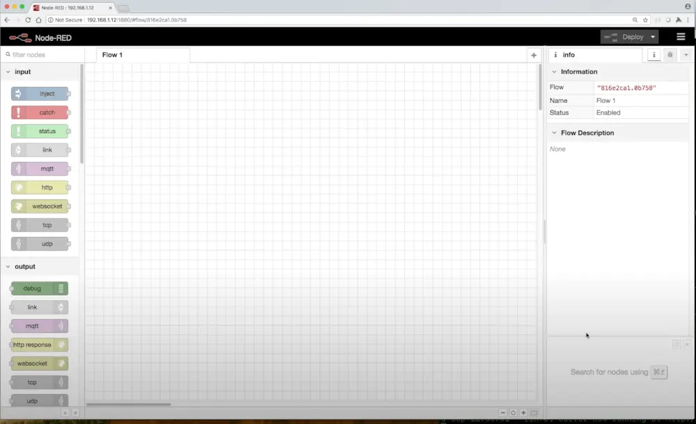
This is a drag and drop interface, you select nodes for your flow from the available options to the left.
Modeling the Traffic Light States
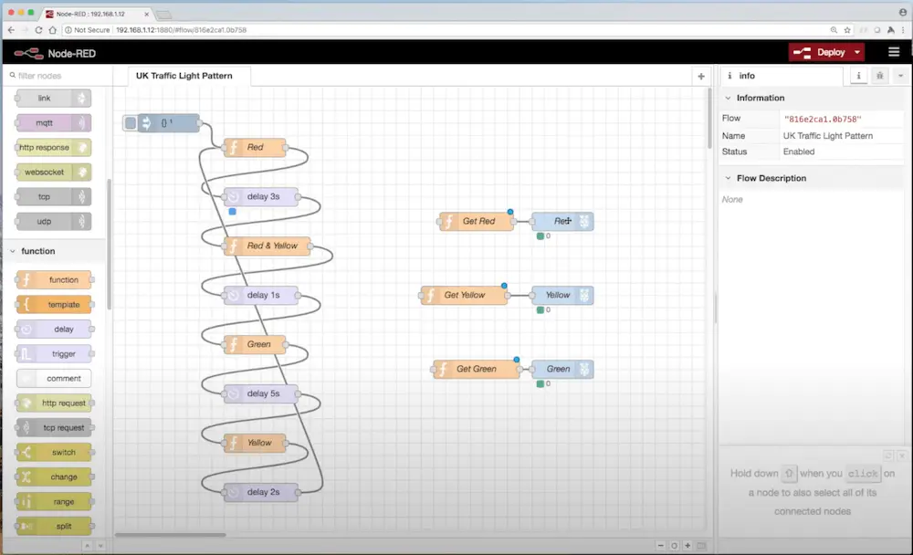
We already know what the states for our application are - a traffic light can be in either the red, red + yellow, green, or yellow states. We’ll model each of these in Node RED using a “function” Node. The function node allows us to write arbitrary JavaScript code for the step in the flow that it represents and we’ll want to do that later. So, we’ll drag a function node from the area on the left into the flow for each of our states:
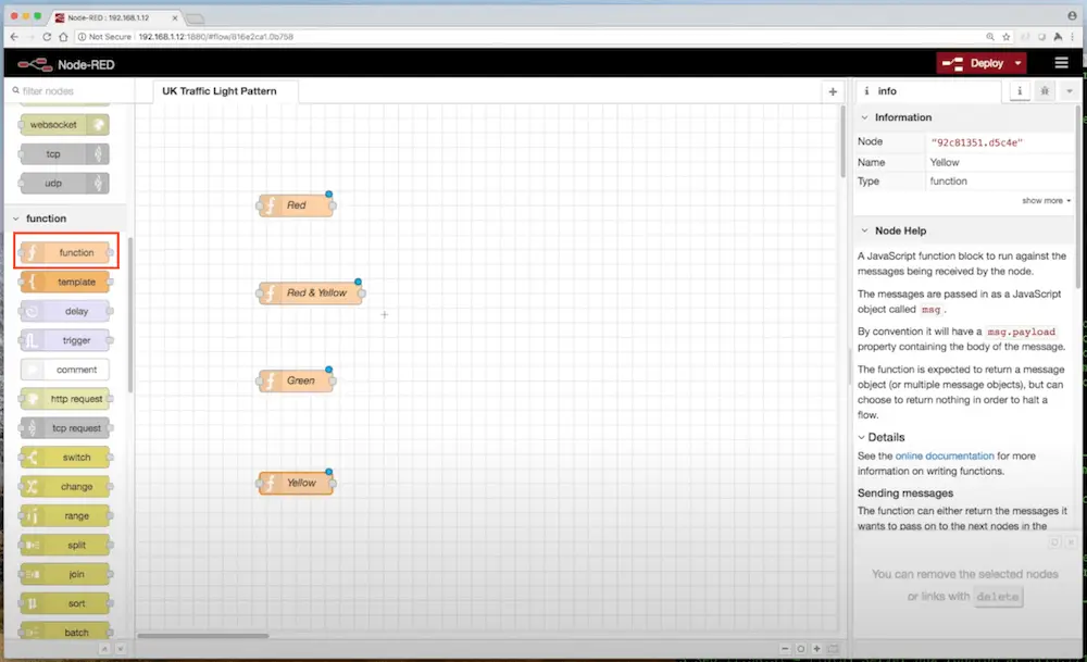
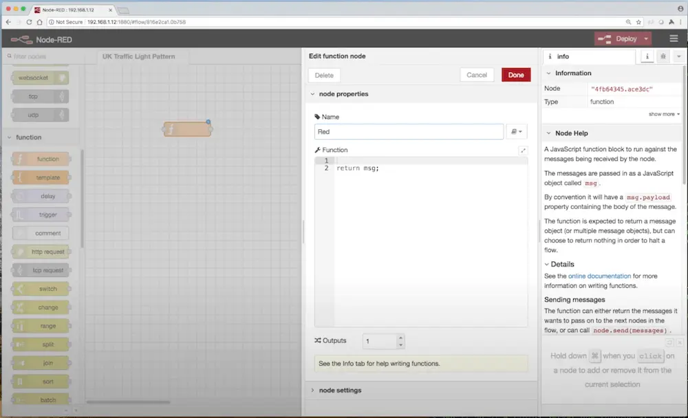
As you can see, I’ve named these nodes to show which lights should be on in each state. To do that, click on the node and set the name in the dialog that appears. We won’t worry about adding code in the “function” part of the dialog just yet.
Traffic lights don’t just transition from one state to another immediately… they generally have variable delays between states. The red light stays on for a few seconds before transitioning to the red and yellow state and quickly onto green etc. Node RED has a “delay” node that we can use to model this. Here, I’ve dragged a delay node into the flow after each state:
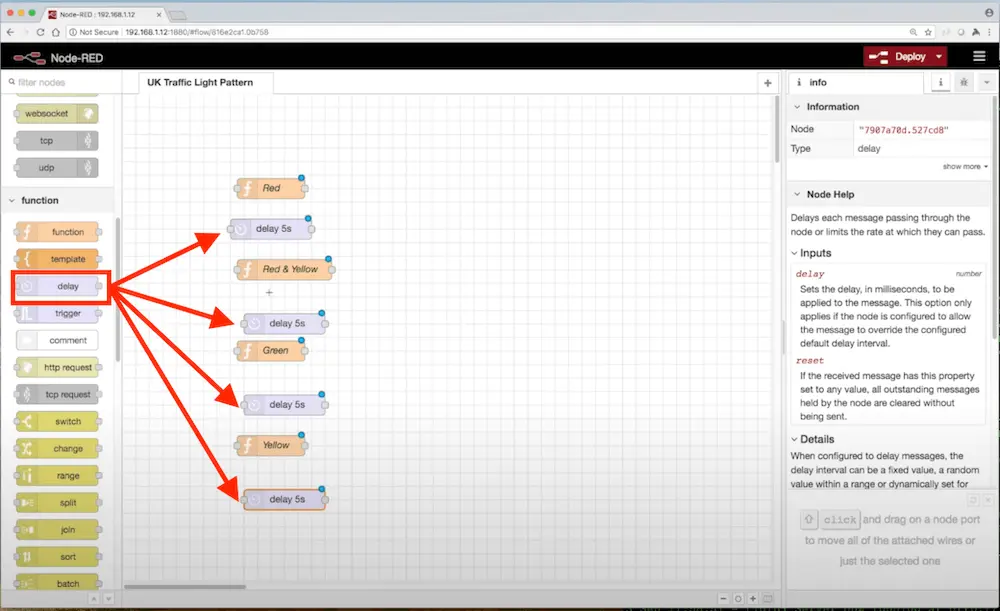
Note that each delay has a default of 5 seconds. We don’t want all of our delay nodes to wait for the same amount of time like this, as that’s not how traffic lights work. We’ll come back and fix that later.
Connecting the States Together
Right now, we can infer the order of states by reading the flow top to bottom… red then a delay then red and yellow then a delay etc. As humans, we know that the light sequence will go back to the red state at the top when the delay at the bottom is over. Node RED doesn’t know any of this, as the placement of the nodes on the screen is totally arbitrary.
To tell Node RED how each node relates to the others, we’ll need to add “connectors” between them. Connectors are added by clicking the circular icons to the right of each node and dragging a connector line to the circular icon to the left of the next node. The right side is for output, the left for input. Here I’ve connected everything together and you can follow the flow from the red state by moving right and keep going until you eventually arrive back at red:
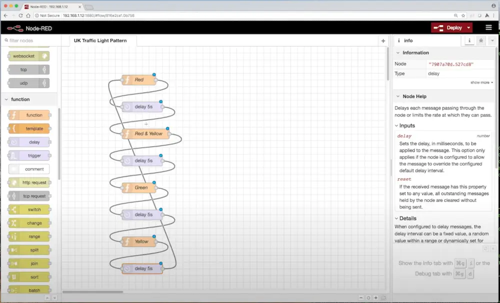
We now have an infinite loop, but for once that’s actually what we wanted to achieve :)
Configuring the State Transition Delays
Let’s fix those delays so they’re not all equal length… clicking a delay node shows its properties dialog. Here, we can change the delay time:
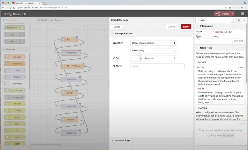
I went with a 3 second delay between red and red & yellow, a 1 second delay before green, then kept the 5 second delay after green. Finally I shortened the delay between yellow before we transition back to red to be 2 seconds. Changing the delay node times updates their labels in the flow to show the new delays too - handy so you don’t have to dig into the properties dialog to see this!
Where to Start?
Everything’s connected and we have our delays configured how we’d like them, so when we run the flow we should get a realistic set of transitions that behave like a traffic light. However, there’s nothing telling Node RED where the flow actually starts - we know the light starts with the red state, but it needs to be told that. To do this, we’ll add an “inject” node and connect that to the red state:
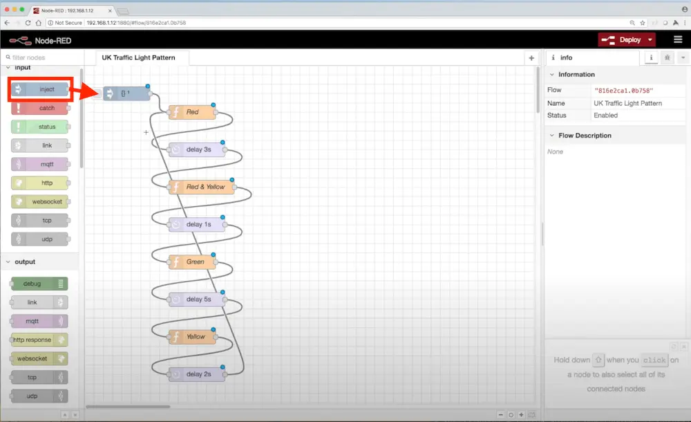
As with other nodes, clicking the inject node displays a properties dialog. I set the inject node to fire once, after 0.1 seconds. So when we start the flow, it will begin with the inject node then almost immediately move to the red function node / state and from there enter the infinite loop described by our connectors.
We’ve now essentially built a finite state machine in Node RED that describes the operation of a UK pattern traffic light. What we haven’t done yet is anything Raspberry Pi specific that would set the LED traffic light LEDs to be on or off appropriately for each state. Let’s tackle that next.
It’s Time to Light the Lights
Each of the three lights that make up a set of Low Voltage Labs traffic light LEDs is connected to the Pi using a GPIO pin. Pi GPIO pins can be used either for input (think a button or switch) or output (think a buzzer or light). In this case, we have three outputs. When installed on the Pi, Node RED comes with nodes for both GPIO inputs and outputs. We’ll want to drag three output nodes into our workspace:
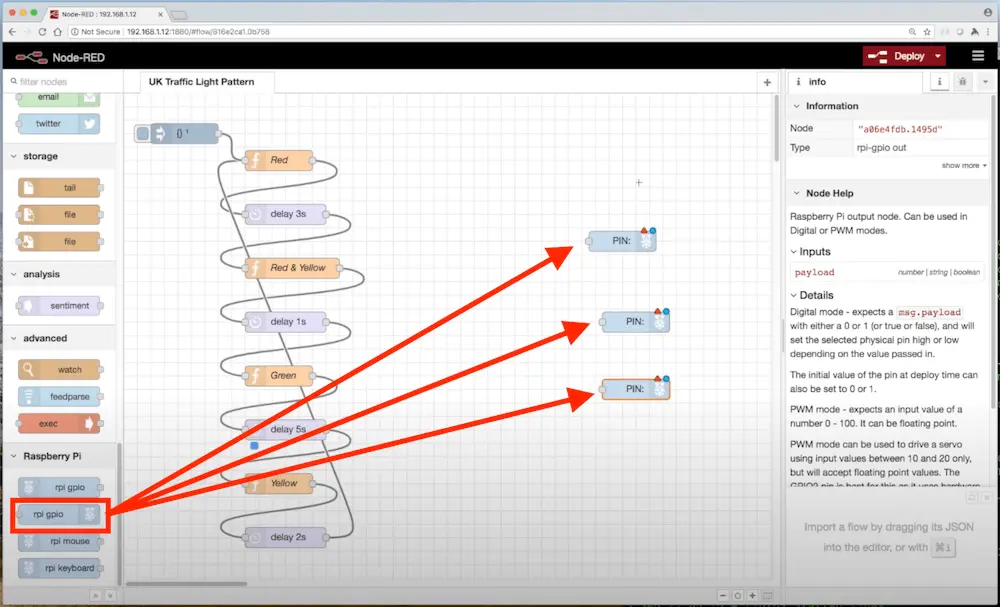
Then click on each one to configure their properties:
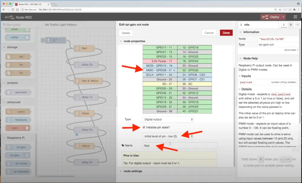
Here, we’ve set the GPIO pin to be pin 9 (the red LED is connected to that). We’ve also set the initial state at start up to be 0 (off) and named the node “Red”. We’ll do the same for the other two, yellow being on pin 10 and green on 11. Note that Node RED has a nice table layout which matches the physical organization of the pins on the Pi board itself.
At this point, there’s no connection between our state machine nodes on the left, and the nodes representing the LED hardware on the right. Each function node representing a state needs to pass information to all three GPIO output nodes, telling them whether the LED should be on or off in that state.
Clicking one of the function nodes displays its properties. Selecting the “Red” function node, we’ll add some code to set msg.payload to an object describing the state that each of the three LEDs needs to be in when we’re in the “red” state. (Node RED expects nodes to communicate by returning a message object containing a payload key):
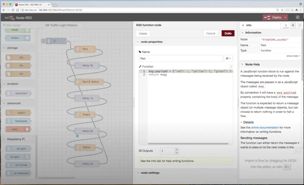
So for the red state, the code is:
msg.payload = { "red": 1, "yellow": 0, "green": 0 };
return msg;
Here, 0 represents off, and 1 on. We’ll do this for the other function nodes that represent each state, for example “Red & Yellow” would be:
msg.payload = { "red": 1, "yellow": 1, "green": 0 };
return msg;
We could now connect each function node to all three GPIO output nodes, and the message containing the desired LED states would be sent to each of them. There’s a mismatch here though, because we have an object describing the state of all three LEDs, and the GPIO output nodes expect to receive a simple 0 or 1 message that will cause them to set the GPIO pin to be on or off. This is the action that actually switches the LED on and turns it off again.
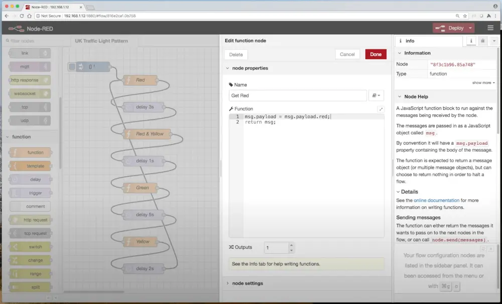
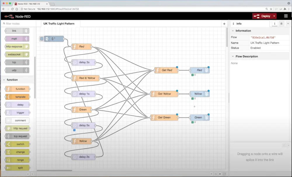
What we need “in front of” each GPIO output node is another function node, that will receive the object describing the overall state of the lights, and pass on only one of the values to the GPIO output node. So, we’ll add three function nodes placed between our state machine nodes and the GPIO nodes. One of these will pull out the red value from msg.payload, another then yellow and the third the green. Each will then return a message whose payload is simply that value, which we can then connect directly to the relevant GPIO output node. Here, we’re configuring the function node that will pass on the red value to the red GPIO output node:
Having added similar function nodes to get the yellow and green values from the state object, then connected their outputs to the inputs of the GPIO output nodes, we have:
Next up we need to make the final connections! Each state over on the left needs to be connected to each of the “Get Red”, “Get Yellow” and “Get Green” nodes, so that the message containing the overall state of the LEDs is sent to each. We do this by adding a connector from the right side of each state function node to each of the three “Get …” function nodes. The diagram gets a little messy, but when done it looks like this:
We’re all set, but how do we get it up and running so we can see some LED light action?
Running the Flow
It’s finally time to run the flow! To do this we click the “Deploy” button:
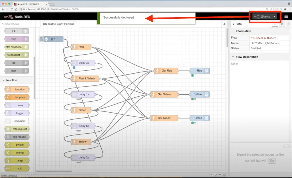
Node RED will then start at the ingest node, wait the 0.1 seconds we configured, then run the red state node, and follow the connectors. The red state node emits a message object having just the red light set to 1, and this goes to all three “Get …” nodes. They read the part of the message that’s for the LED they represent, and convert it to a 0 or 1 that is send to the relevant GPIO output node. Meantime, the state machine part of the flow sits in a delay node for the configured number of seconds before moving to the next state. Node RED shows which nodes are active at any given time using blue squares, and we can see whether the GPIO pins are set to 0 (off) or 1 (on) as the status is shown next to each.
Now you’ve read about how this example was built, you might want to watch the video version of this build where you can see me perform each complete step:
If you’d like to try this project out without building your own flow from scratch, I used Node RED’s export option (in the main menu) to generate a JSON file for mine and made it available on GitHub. You should be able to take this and use the import option (also in the main menu) to load it up and try it out on your own Pi. Also, this was my very first attempt at using Node RED, so if you think I’m doing it wrong and can offer some better ideas I’d love to hear from you (contact page)!
Hope you enjoyed this article and accompanying video!
 Radio Controlled Car and Coffee Fun