 Simon Prickett

Here in San Diego, we have a monthly meetup called Fundamental JS. This is part of the wider San Diego JS family of meetups and is a favorite of mine because it focusses on core JavaScript rather than the framework du jour. It’s also held very close by to where I live downtown, so is very convenient to get to.
I try and speak at these events periodically, usually about some JavaScript language feature or Node.js basics. In the past I’ve spoken about Server Sent Events, which eventually became the most popular blog post I’ve written by a long way! I had wanted to talk about the Raspberry Pi and physical computing for this group for quite a while, so approached the organizers about a talk where I’d explore building a smart plug type product with a Node.js back end and basic HTML / JavaScript front end. I got the go ahead to do this, so then had to make it happen!
Your support helps to fund future projects!
I wanted to demonstrate control of “real world” things, so rather than using low voltage LEDs as I have in previous projects I decided to go for regular mains electric lights this time. Here in the USA, these run on 110v electricity which is obviously way more than the 3.3-5v that the Pi operates with. Fortunately, there’s a range of add on HAT boards available for the Pi that solve this issue by providing a set of relays that the Pi can safely control without being exposed to the higher voltage mains electricity itself.
Demonstration
Here’s a video of the front end being used to turn the lights on and off which then cuts to me presenting the project at the Meetup event, using Postman to control the lights by making calls to the Node.js API.
Thanks to Suze Shardlow for capturing the video from the Meetup talk.
Building the Hardware and Software
I did some Googling and ended up picking this HAT which has 3 independently controllable relays on it. It’s made by Electronics Salon and can be bought from Amazon.
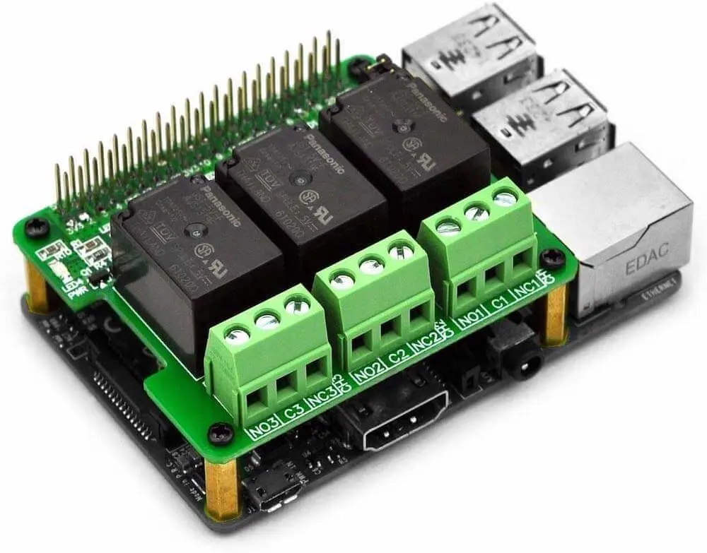
I liked this one because it also has pass through pins for the GPIOs… a lot of HATS use all 40 pins to connect to the Pi, but only require connection to a few of them - blocking the others from other uses… I like that with this one you still get easy access to the rest of the GPIOs to attach other things, and this is something I hope to try in future.
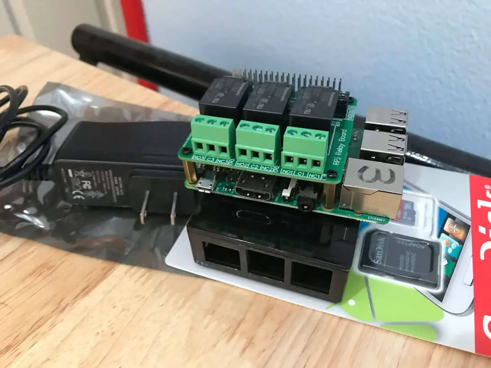
I own several Raspberry Pi 3 from previous projects, so using one of those made a lot of sense. The relay hat fits on any Pi with 40 pin GPIO, so you could use a 2, 3, 4, Zero, Zero W if that’s what you have. There’s nothing special about the operating system setup required. I used the latest Raspberry Pi OS Lite (download here). Also, fitting a HAT to the Pi is really simple - just push it onto the 40 pin GPIO and you’re done. The relay hat came with some stand offs for stacking other hats on top of it - I used a couple of these to make some legs for the side of it that wasn’t connected to the GPIO pins:
Once I had the operating system installed on the Pi, I wanted to get an up to date version of Node.js installed on it so I could use some ES6 language features (Fundamental JS meetup discourages the use of frameworks, but is all about using the latest vanilla JS). I’ve written about how to get a newer Node.js version onto a Pi before, if you’re interested in doing that check out my article here.
To build out a circuit to control three lightbulbs, I needed some additional hardware…
- 3 cleat style light sockets - these can be screwed down to mount them, and have simple neutral and live wire connecting screws on the side. They’re also nice and cheap.
- A length of lamp cord - a cheap way to get some cord with a wall plug on it, and also to cut up and wire the light sockets to the relays.
- A 6 position terminal strip, to make connections without soldering or using wire nuts. I needed 6 positions to split the single live and neutral connections coming in from the wall plug on the lamp cord 3 ways, one for each bulb.
- 3 light bulbs, just any standard fitting ones. I chose three different colored ones from Home Depot.
- A piece of wood to bolt the terminal strip and light sockets down to. I got something for a couple of Dollars again at Home Depot.
- Some wood screws for mounting the terminal strip and light sockets to the wooden base.
Obviously, the Pi also needed a Micro SD card and power supply :)
Wiring up the Lights
Each light needs to be connected to both the live and neutral wires that ultimately connect to the mains electric plug. To do this, I ran the live from the wall plug into the terminal block, splitting it into 3 of the inputs. I then wired the other side of each of these terminals into the relays on the Pi HAT, then out to the bulb holders. This puts the relays into the circuit as switches for each of the bulbs.
The neutral wire from the wall plug then goes into the terminal block, is also split 3 times, and comes out of three of the terminals to the bulb holders. The neutral wires don’t need to go through the relays.
Here’s a poorly drawn sketch of the wiring arrangements:

After I’d connected all the wires up and screwed the various components to the wooden base, the hardware side looked like this:
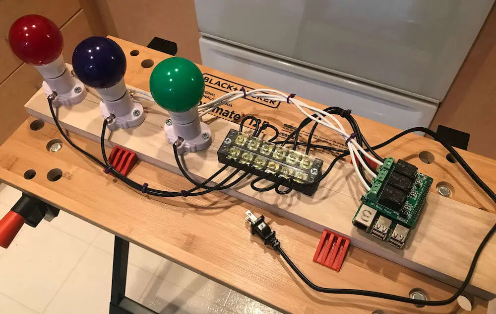
I used some cable ties to keep the wires together / slightly tidier. I wanted to get a yellow bulb to make a traffic light, but the only yellow ones Home Depot had were insect zapper types, so I got blue instead…
In this photo, the red bulb is wired to relay #1, the blue to #2 and the green to #3.
Software
As this project was built for a presentation at the Fundamental JS meetup, the software needed to meet a couple of basic criteria:
- Written in JavaScript.
- Avoid use of frameworks where possible.
This was easy enough to accomplish using:
- Node.js for the back end with the built in
httpmodule. - Vanilla JavaScript / HTML / CSS for the front end.
- For interfacing with the Raspberry Pi GPIO pins, I did use the excellent
onoffmodule though.
As we’re aiming to build something like a smart light switch, I wanted the software to consist of:
- A back end API supporting calls to turn each light (relay) on and off independently, as well as being able to retrieve the status of each light.
- A basic web front end that shows the status of each light, and provides buttons to turn them on and off. This should be served from the same Node.js process on the Pi as the API is, and interact with the relays by making API calls.
Back End / API
For the back end, I decided these endpoints would be suitable. Retrieve on / off status of a relay (light):
GET http://<host>:<port>/relays/<relayNumber>
Where:
<url>is the hostname or IP of the Raspberry Pi.<port>is the port that the back end is listening on.<relayNumber>is a number between 1 and 3 to specify which relay we’re interested in.
This endpoint should simply return the string true if the relay (light) is on, and false if it’s off.
To change the state of a relay:
POST http://<host>:<port>/relays/<relayNumber>
Send a JSON body:
{
  "state": <true|false>
}
So, send true to turn the relay on, and false to turn it off. These calls return true or false to the caller, depending whether the relay is on or off as a result of making the call.
The back end code is contained in a single file that works by setting up a http server on port 8888 and listening for all HTTP requests. This server first captures the request body (without using frameworks, Node’s http module requires us to do that by receiving the request body in chunks and assembling them into a string then attempting to parse that string as JSON). Here’s the code, followed by a brief explanation of how it works:
Once the request is fully received (request.on('end')), the server checks if it is a HTTP GET or POST, and replies with a 500 error if not, as it doesn’t know how to deal with DELETE, PUT etc.
The server then performs one of two jobs, depending on the requested URL. If the URL was /, it opens up the file index.html and sends that back to the client. This is how the front end web page is served. That page contains the front end’s JavaScript code too, so there’s no need to handle requests for any .js files.
If the URL contained /relays/1, /relays/2 or /relays/3, the server works out which of the three relays is required, and gets the onoff GPIO object for that. These are kept in an array where relay 1 is the 0th member of the array, relay 2 is the 1st etc.
If the request was a POST, the server looks in the body to see if the requested state was true or false, and calls the writeSync function on the appropriate relay GPIO object to turn the relay on or off. writeSync expects an integer not a boolean, so we send 1 for true, and 0 for false.
If the request was a GET, and also for all POST requests, the server then calls the readSync function on the appropriate relay GPIO object to get its on/off state, translating the 1 or 0 response to true or false and returning that to the client.
For any GET or POST request that has a URL other than /, /relays/<1-3>, the server response with a 404 not found.
If you’re interested in how the onoff module controls GPIO pins, here’s the relevant part of the documentation – the relays act like a LED, an output that can be turned on and off.
The relay HAT associates the three relays with GPIO pins 26, 20 and 21 which you can see at the start of the server code. The nice thing about the hat hardware is that you can reconfigure this to other pins if you want to add additional hardware to the Pi that uses any of these default assignments. This is accomplished by attaching jumper wires to the HAT.
Front End
The front end is very simple, has no styling and is contained entirely in a single index.html file. This is partly because the back end “web server” in Node.js is so basic that I’d have to write extra code to serve CSS and JavaScript files. That wasn’t the point of this demo, so I didn’t do that :)
The front end does two things:
- Displays the current state of each relay. As there may be many clients connecting to the back end and changing the relay states, the front end polls the back end for status by calling
GET /relays/<relayNumber>for each of the three relays every second. This isn’t efficient or scalable, but gets the job done. A better implementation would probably use web sockets or server sent events, and also have a back end API endpoint that returns the status of all three relays in one call. - Allows the user to change the state of each relay. This is achieved by having an on and off button for each of the three relays. When pressed, these buttons call a JavaScript function that uses the button’s
idattribute to determine which relay number to send an API POST request for and whether to usetrueorfalseas the desired state in the POST body.
The code’s pretty simple, and should be self-explanatory. I also used ES6 JavaScript because it’s 2020 and we should all have a modern browser and not have to transpile stuff:
If you want to play with the code yourself, or just look it over, I published it here on GitHub and you are free to use it as you see fit.
If you like the sound of the Fundamental JS meetup, it’s held on the 4th Wednesday of each month and can be found on the San Diego JS Meetup.com page. Hope to see you at an upcoming event!
(Main photo by Sergey Svechnikov on Unsplash).
 Exploring JavaScript Generators with Redis Sets