 Simon Prickett

I recently noticed that Adafruit sells low cost ($3.95) wired door sensors that basically act as a switch — if the magnet from one part of the sensor is placed in close proximity to the other part, the switch circuit closes. As the magnet in the part that you’d normally attach to a door moves away (because the door swings open), the switch circuit opens. If you’ve read my previous Raspberry Pi post, you’ll know I have a few sets of traffic light LEDs, so I thought I’d see if I could do something with these and a door sensor…
Shopping List
We’ll need a few things to build this out, which are…
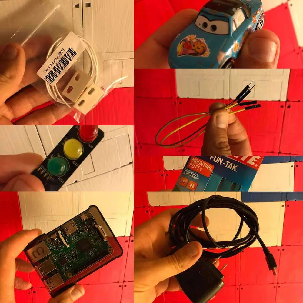
- AdaFruit Door Sensor
- Low Voltage Labs Traffic Lights
- A Raspberry Pi with SD card and OS installed — I’m using the Pi 3, but any model with GPIO headers will do (unless you fancy some extra soldering then you could use the Pi Zero etc)
- A small model car — I’m using a Pixar Cars Mazda Miata :), anything Hotwheels or similar will do
- A pair of jumper wires (either male to female or female to female — doesn’t matter as we’ll be cutting one end off to solder to the door sensor wires, so you just need one female end to attach to the Pi GPIO headers without soldering them)
- Some Loctite Fun Tak or similar mounting putty (to hold things in place)
- A power supply for the Pi (Raspberry Pi 4 requires a different USB C power supply)
We’ll also need to do a little soldering, so you’re going to want a soldering iron and solder.
Hardware Setup
As delivered, the door sensor comes with bare wires… we could solder these directly to the GPIO pins on the Pi, but for a more re-usable solution it’s better to use the jumper wires…
Your support helps to fund future projects!
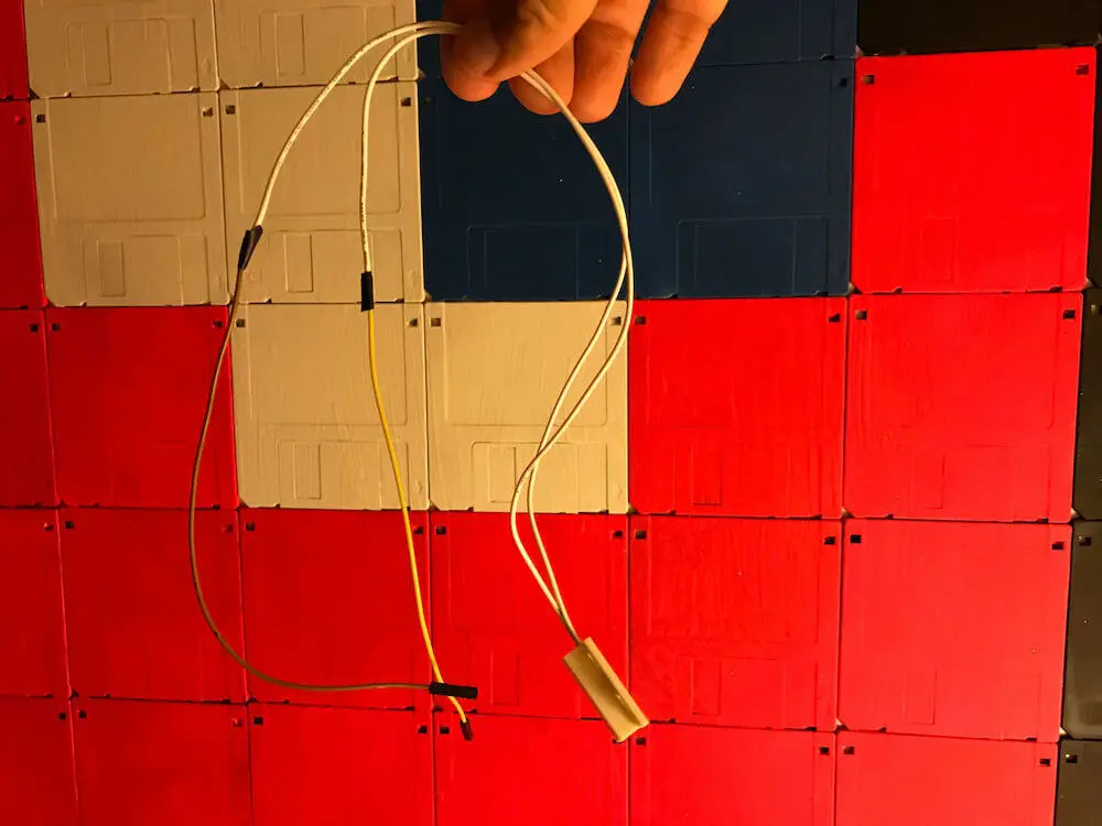
One end of the jumper wire provides a female connector that goes onto the pin on the Pi. The other end is a male connector — cut that off and strip the insulation back to expose the cable, then solder it to one of the exposed wires on the door sensor. Repeat with a second jumper, and use some electrical tape to cover the solder. You should end up with something that looks like this:
Next, we can attach the traffic lights and door sensor wires to the GPIO pins on the Pi. The traffic lights require 3 pins followed by a ground pin due to the way that their connector works. The door sensor requires one of its wires to be attached to ground, the other to any usable pin. As the door sensor is a simple switch, it doesn’t matter which wire is connected to ground.
The code sample I’ll be using will need you to connect the lights and door sensor to the pins shown below (red = traffic lights, yellow = door sensor).

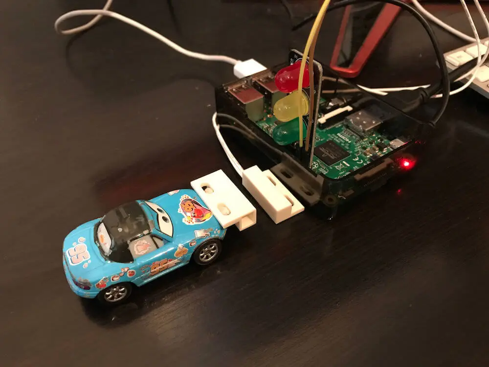
Having got everything wired together, use the Fun Tak to hold the door sensor down to the desk in front of the Raspberry Pi and the door sensor magnet to the front of the car like so:
Code & Operating System Setup
We don’t need to do anything particularly special when setting up the Raspberry Pi — I just installed the latest Raspberry Pi OS Lite operating system (install guide here) and set up my wifi. Then, we need to install a couple of extra software packages to allow downloading of my sample code from GitHub, and to give Python access to the GPIO pins on the Pi. Enter the following at the command line when logged in as the pi user:
sudo apt-get install python-dev python-rpi.gpio git
Answer “Y” when asked if you want to install additional packages.
The traffic lights operate in the same manner as in my previous posts, each of the red, yellow, green lights maps to a GPIO pin, and can be turned on and off with:
GPIO.setup(<pin>, GPIO.OUT)
...
GPIO.output(<pin>, <True = on, False = off>)
The door sensor is a little different. As a switch, it operates using one pin (the other wire is connected to ground). It is also an input rather than an output, and we need to set the software pull up resistor to stop the value of the pin floating:
GPIO.setup(DOOR_SENSOR_PIN, GPIO.IN, pull_up_down = GPIO.PUD_UP)
What we want to do with our code is detect when the door sensor changes state, then update the traffic light LEDs accordingly — if the door is closed (magnet attached to the car is close to the sensor), we want the red light on and green light off. When the door opens (magnet attached to the car moves away from the sensor), we want to turn the green light on and red light off. We won’t be using the yellow light in this demo, other than to initially make sure that it is turned off.
The complete code to do this is as follows:
import RPi.GPIO as GPIO
import time
import sys
import signal

# Set Broadcom mode so we can address GPIO pins by number.
GPIO.setmode(GPIO.BCM)

# This is the GPIO pin number we have one of the door sensor
# wires attached to, the other should be attached to a ground pin.DOOR_SENSOR_PIN = 18
# These are the GPIO pin numbers we have the lights attached to
RED_LIGHT = 9
YELLOW_LIGHT = 10
GREEN_LIGHT = 11

# Initially we don't know if the door sensor is open or closed...
isOpen = None
oldIsOpen = None

# Clean up when the user exits with keyboard interrupt
def cleanupLights(signal, frame):
    GPIO.output(RED_LIGHT, False)
    GPIO.output(YELLOW_LIGHT, False)
    GPIO.output(GREEN_LIGHT, False)
    GPIO.cleanup()
    sys.exit(0)

# Set up the door sensor pin.
GPIO.setup(DOOR_SENSOR_PIN, GPIO.IN, pull_up_down = GPIO.PUD_UP)

# Set up the light pins.
GPIO.setup(RED_LIGHT, GPIO.OUT)
GPIO.setup(YELLOW_LIGHT, GPIO.OUT)
GPIO.setup(GREEN_LIGHT, GPIO.OUT)

# Make sure all lights are off.
GPIO.output(RED_LIGHT, False)
GPIO.output(YELLOW_LIGHT, False)
GPIO.output(GREEN_LIGHT, False)

# Set the cleanup handler for when user hits Ctrl-C to exit
signal.signal(signal.SIGINT, cleanupLights)

while True:
    oldIsOpen = isOpen
    isOpen = GPIO.input(DOOR_SENSOR_PIN)

    if (isOpen and (isOpen != oldIsOpen)):
        print "Space is unoccupied!"
        GPIO.output(RED_LIGHT, False)
        GPIO.output(GREEN_LIGHT, True)
    elif (isOpen != oldIsOpen):
        print "Space is occupied!"
        GPIO.output(GREEN_LIGHT, False)
        GPIO.output(RED_LIGHT, True)

    time.sleep(0.1)
We detect a change in the door sensor state by remembering its state from the previous loop iteration and comparing it to that of the current iteration. The sensor should “close” and “open” as the car (our door here) is moved towards then away from the sensor:
We’re now able to monitor whether or not the car’s “parked” and set the lights to show the space as occupied or available. This isn’t how we’d do a real parking system as it requires the car to have a magnetic tag on it, but it makes for an easier demo of how to work with the door sensor than attaching it to a door :)
Double Down!
The Pi has lots of GPIO ports, enough to support adding a second door sensor and set of traffic lights, so we can monitor two of them…
Adding a second door sensor requires another ground pin, and any other GPIO. We could solder the ground wires for both door sensors together and use three pins not four, but as we have plenty here I didn’t do that.
Adding another traffic light requires a sequence of one ground pin followed by three GPIOs, as the traffic light connector is set up to be attached to that order of pins.
Moving things around from the single switch demo, we can fit two sensors and two lights onto the Pi using the following arrangement (again, yellow highlighting shows where the door sensor pins go, and red is for the traffic lights with the arrows showing the direction in which the lights face):

Now we need to essentially duplicate the code we have to run two independent setups, which we’ll name “left” and “right”. So the main code loop would then look like:
# Not shown, additional definitions for LEFT and RIGHT pin numbers
while True:
    leftOldIsOpen = leftIsOpen
    leftIsOpen = GPIO.input(LEFT_DOOR_SENSOR_PIN)

    rightOldIsOpen = rightIsOpen
    rightIsOpen = GPIO.input(RIGHT_DOOR_SENSOR_PIN)

    if (leftIsOpen and (leftIsOpen != leftOldIsOpen)):
        print "Left space is unoccupied!"
        GPIO.output(LEFT_RED_LIGHT, False)
        GPIO.output(LEFT_GREEN_LIGHT, True)
    elif (leftIsOpen != leftOldIsOpen):
        print "Left space is occupied!"
        GPIO.output(LEFT_GREEN_LIGHT, False)
        GPIO.output(LEFT_RED_LIGHT, True)
    if (rightIsOpen and (rightIsOpen != rightOldIsOpen)):
        print "Right space is unoccupied!"
        GPIO.output(RIGHT_RED_LIGHT, False)
        GPIO.output(RIGHT_GREEN_LIGHT, True)
    elif (rightIsOpen != rightOldIsOpen):
        print "Right space is occupied!"
        GPIO.output(RIGHT_GREEN_LIGHT, False)
        GPIO.output(RIGHT_RED_LIGHT, True)

    time.sleep(0.1)
The end result of this is that we now have two independently monitored parking spaces…
Hopefully you found this a fun use of some simple hardware components. If you want to grab the complete code and use it yourself, it’s available on GitHub.
I’d love to hear what you’re up to with the Raspberry Pi — get in touch via the Contact page. If you enjoyed this article, please share it far and wide!
 Playing with Raspberry Pi: Traffic Lights with a Finite State Machine