Sorta like Simone’s, but smaller! One of my favorite Youtube channels is Simone Giertz’s — she documents her attempts to build robotic helpers to assist with everyday tasks. Part of the point of the channel is that these often fail to perform as intended but fun and learning comes from the building process. If you want to hear more from Simone about why you should build useless things then I’d suggest watching her TED Talk on the subject.
Anyway, Simone recently launched a Kickstarter campaign to fund the building of a yearly task tracker board with 365 buttons — press one each day that you complete a task you’ve set yourself, hopefully forming good habits from doing so. You could use it for example to track a daily exercise goal. Update, December 2022… you can now buy Simone’s finished product direct from her online store - this was initially only for sale to the USA, but now has international shipping as of late 2023!
I really liked this idea, and it got me thinking about building something like it on a smaller scale for my younger son who is seven years old. Rather than tracking a whole year’s worth of progress, I figured a week would be a suitable period and set about planning a build…
Your support helps to fund future projects!
Before diving into the build details let’s take a quick look at the finished product:
Hardware
Buttons
I liked Simone’s idea of having the tracker as a physical thing that could be touched, wall mounted and glanced at easily. This ruled out building it as an online tool or app because I didn’t want my son to have to go turn on his device, boot it up, start a particular app or visit a specific URL to see or record progress. I wanted it to be a much tighter feedback loop for him: complete the task, go to the tool, update status, get immediate gratification.
After a bit of thinking and googling, I decided the cleanest approach to achieve this would be to use LED arcade buttons. These operate both as an input (a nice satisfying button press) and an output (they have a bright LED light built into them that can be turned on and off independently of the pressing of the button). As a bonus they’re also very robust as they’re designed to be hammered hard while playing video games.
Adafruit sells 24mm LED arcade buttons in a variety of colors that fitted my needs perfectly. I decided to use green ones for a nice positive reinforcement of “job done”.
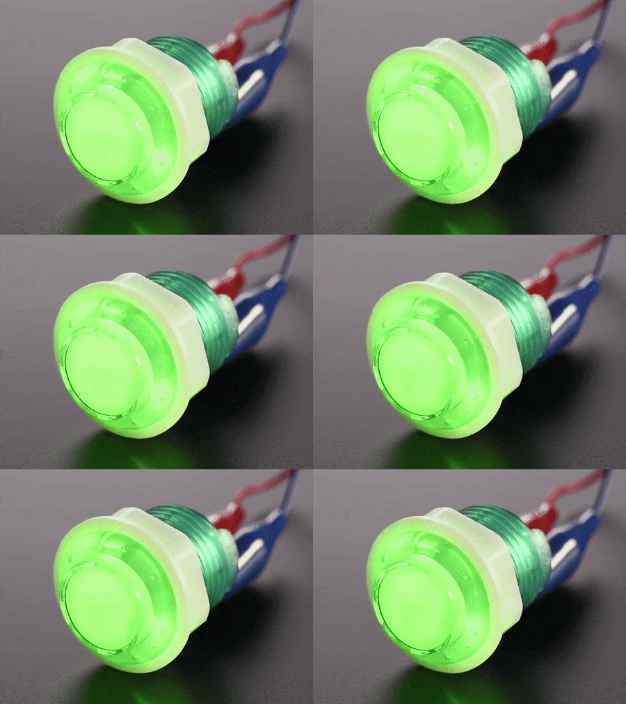
As I wanted to create a weekly task tracker, I needed seven buttons: one for each day of the week. To add a reset function and also to make it two rows of four buttons each I added a single additional red button.
Enclosure
Next up I had to find an appropriate enclosure that I could mount the buttons to and which had enough space to contain all of the associated wiring, power cord and logic board that I was going to need. I had some additional requirements for the enclosure: it needed to be rugged without having sharp edges, easy to open and close to work on but not easy for a child to get into, and easy to drill circular holes into for mounting the buttons.
I took a walk around my local Home Depot store to see if they had anything that might be a good fit. I’ve always found Home Depot employees to be really helpful with the random things I’ve asked their advice about. They came good yet again, directing me to the electrical junction boxes. They have a range of these in different sizes that are basically empty boxes made of PVC that are easy to drill holes in and come with a screw mounted lid. I got one that was 6” x 6” x 4” deep which allowed enough space to lay out my seven buttons. Here’s what it looked like on my workbench after I’d drawn some guide lines on it for drilling:
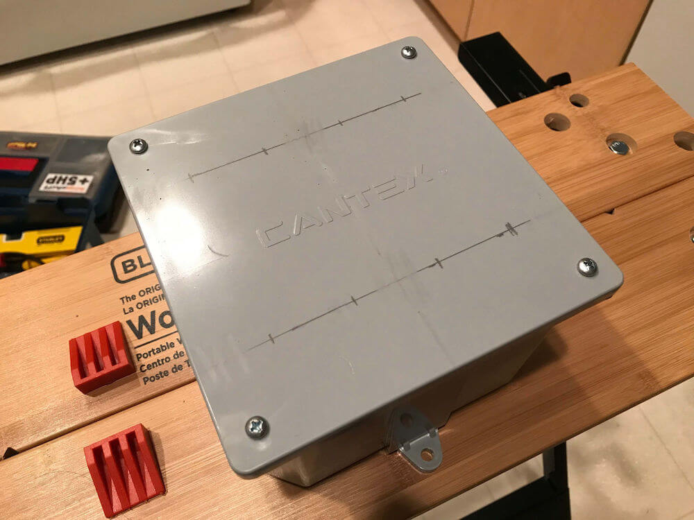
I think it would have been cooler to have a see through lid. This box was relatively cheap, easy to come by and as it turned out very easy to drill holes in without causing cracks (PVC is pretty forgiving).
Wiring
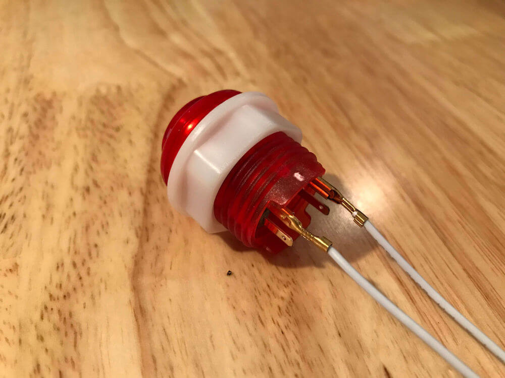
Each arcade button has four wiring terminals on it. The switch function uses two, one of which is ground. The LED function uses the other two with one again being ground. I found that with the majority of the buttons I received, the LED data connection had a red mark on it which helped with later assembly.
The usual method for wiring up these buttons would be by soldering hook up wires to them — I usually use 22AWG solid core wiring as it’s easier to solder than stranded speaker wire. However, my soldering skills aren’t great and I also wanted to see if this could be a more approachable project for children.
To minimize soldering I used Adafruit’s arcade quick connect wires for the data connections. These simply press onto the terminals on the buttons using a spade type connector, no soldering required. I did solder all of the ground connections for reasons we’ll get to at assembly time. Here’s what one of the buttons looks like with the quick connect wires attached to its data terminals:
Logic Board
This component is the brains of the system — it’ll need to be able to receive input from the arcade buttons, send output signals via the LEDs in the buttons and run some custom logic to keep track of task completion.
There are many single board computer or microprocessor board options here, I decided to go with the Arduino Uno because:
- I already had one sitting around doing nothing and it was about time I used it.
- It’s easy to program and has a free integrated development environment.
- It uses 5v so has enough to power the LEDs in the arcade buttons.
- Arduino boards make a lot of sense for embedded projects as there’s no operating system or other complexity — you flash your code onto the board and it just runs it with no appreciable boot up time when the power is turned on.
- Crucially, it has 14 digital data pins… this project needs all of these as we have 7 buttons to read the status of and 7 LEDs to toggle. Each of these will need a unique digital pin.
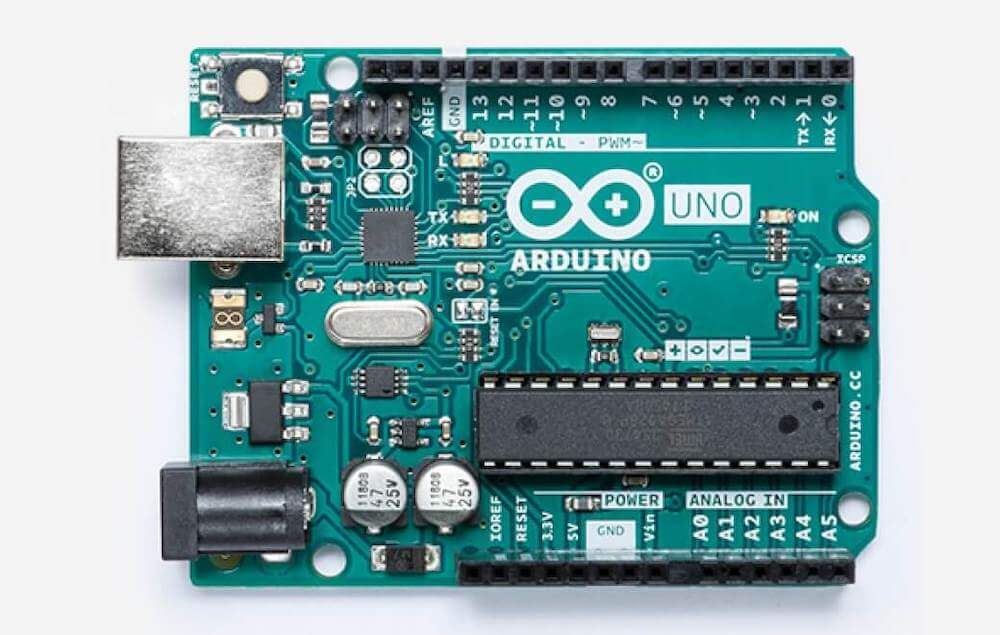
With all fourteen digital pins taken up with the buttons representing the seven days of the week, how does the red (reset) button fit into the picture? Thankfully the Arduino has a separate hardware reset pin that we can wire the button to and this doesn’t use up one of the fourteen digital logic pins. I’ll cover how that works during assembly.
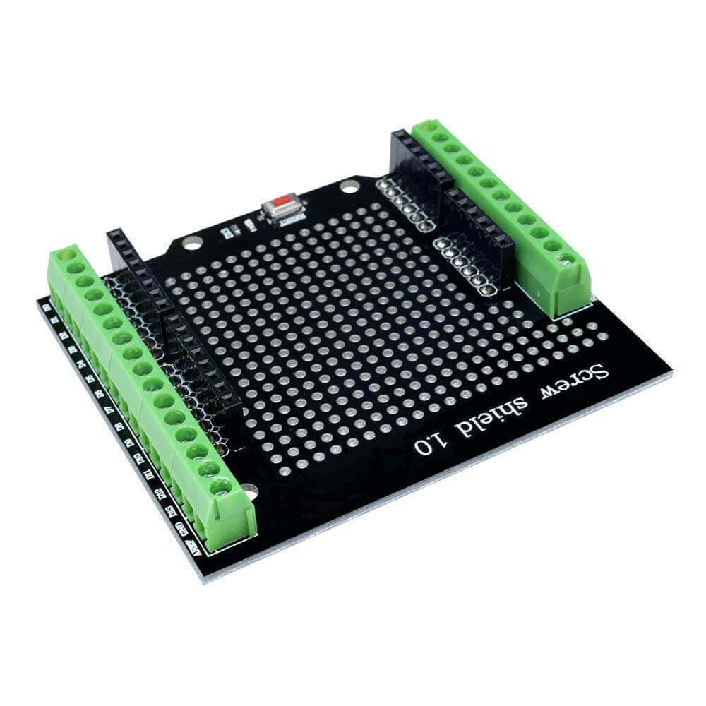
I also didn’t fancy doing lots of soldering to connect fourteen data wires, plus ground and the reset wiring to the Arduino. To avoid that, I added a screw shield, which sits over the Arduino headers and allows you to connect wires by clamping them with screws rather than solder. These are also great for prototyping things as you can rewire things easily.
Power Supply
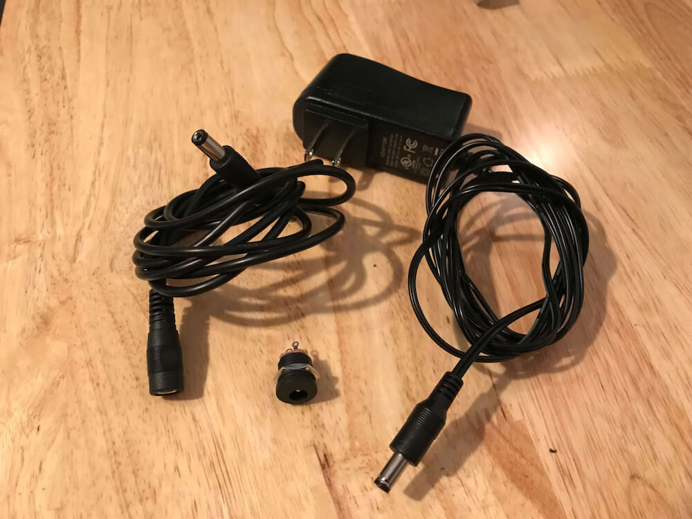
I wanted a single power supply system that would be capable of powering the Arduino and illuminating all seven of the green LED buttons simultaneously. This turned out to be an easily met requirement as Adafruit sells a 12v / 1A power adapter with the right sort of barrel jack for the Arduino. To make things neat and tidy. All in all, the power supply system parts look like this (before some cutting and soldering during assembly):
Assembly
Assembling the hardware was a pretty satisfying phase of the project although it did involve soldering a lot of ground wires together! I measured where I wanted to place the buttons, then used Forstner drill bits to cut precise circles in the PVC junction box — these are designed for this specific job and do it really well!
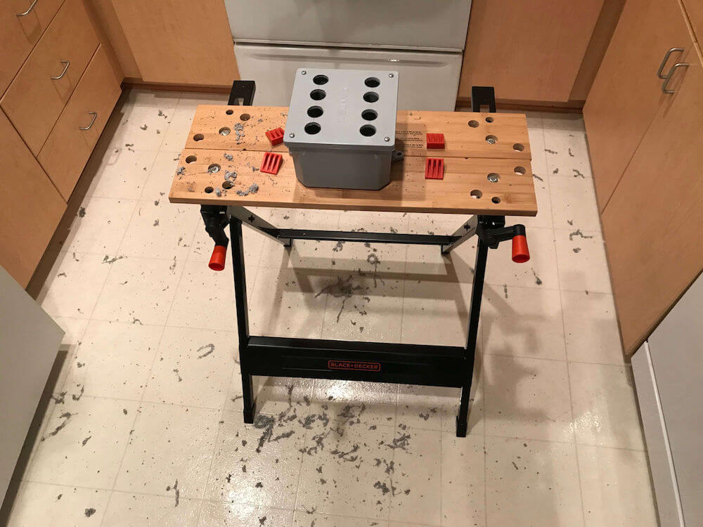
The drilling process did make quite a mess which, although easy to sweep up, could get in your eyes so be sure to use eye protection if trying this! I used a 25mm drill bit and also made a smaller hole in the side of the box for mounting the power jack.
Attaching the arcade buttons is then very simple as they just screw into place with the fitting that Adafruit ships them with:
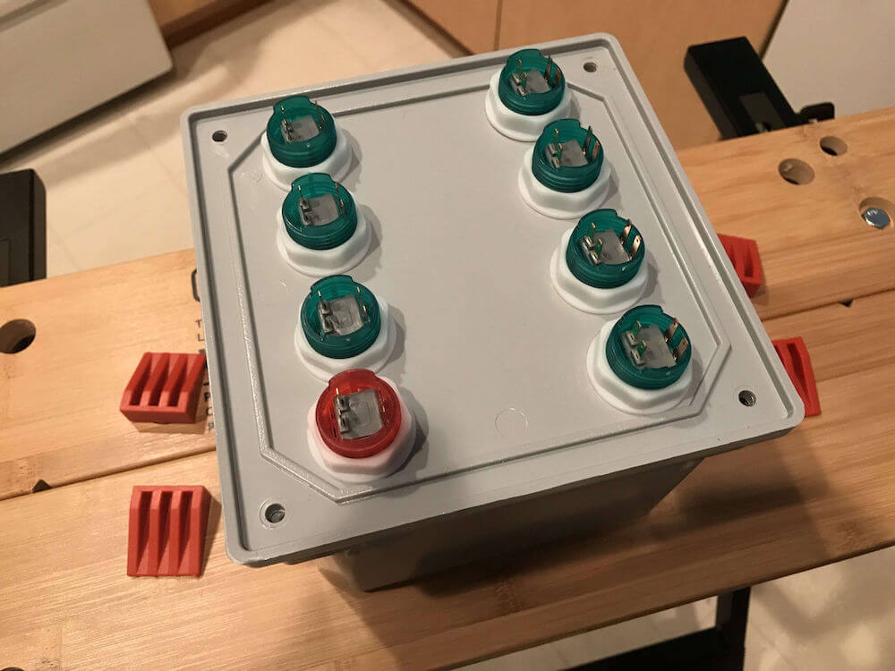
When fitting the arcade buttons I made sure that the terminal with the red paint mark on it was in the top right position for each one, meaning that the wiring setup for each would be as follows:
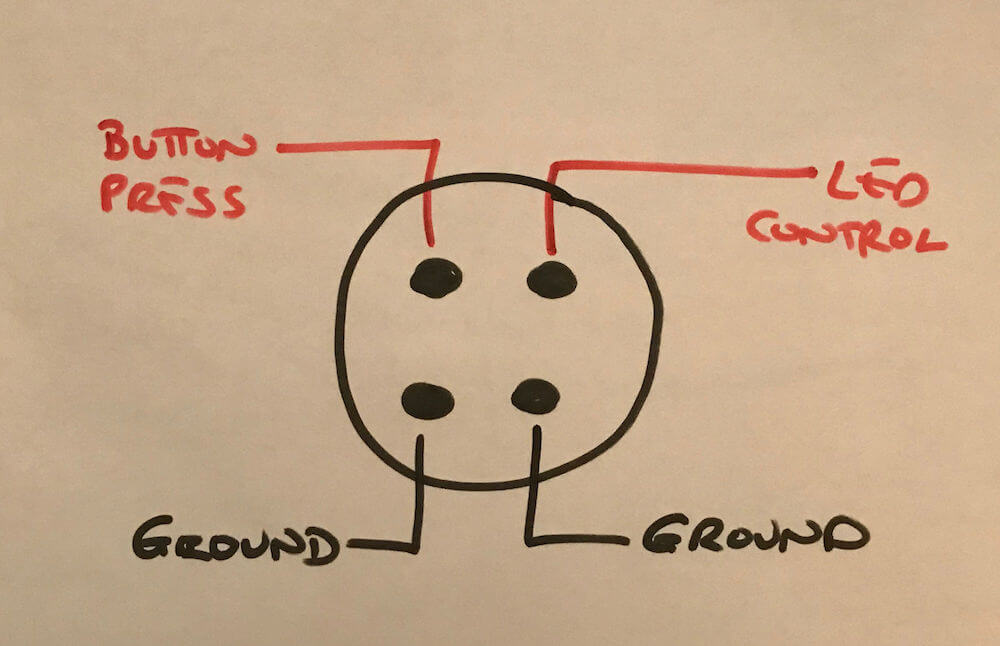
Each of the ground terminals on the buttons needed wiring together so that they were all linked to one to two wires that could be attached to the Arduino’s ground pins (it doesn’t have enough of them otherwise). This involved a lot of messy (as I’m not very good at it) soldering. I then used the quick connect arcade wires for each data terminal on the arcade buttons and ended up with this spaghetti!:
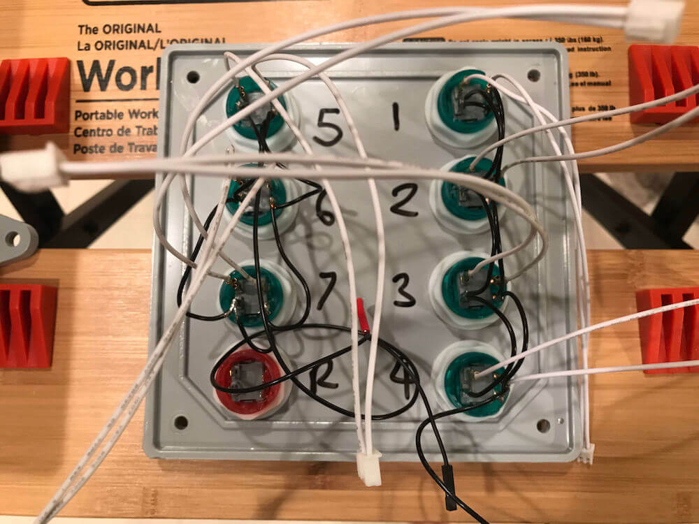
After connecting all the wires to the Arduino (pro tip: making notes on which wire links which digital pin on the Arduino to which function on each button is essential), things looked like this:
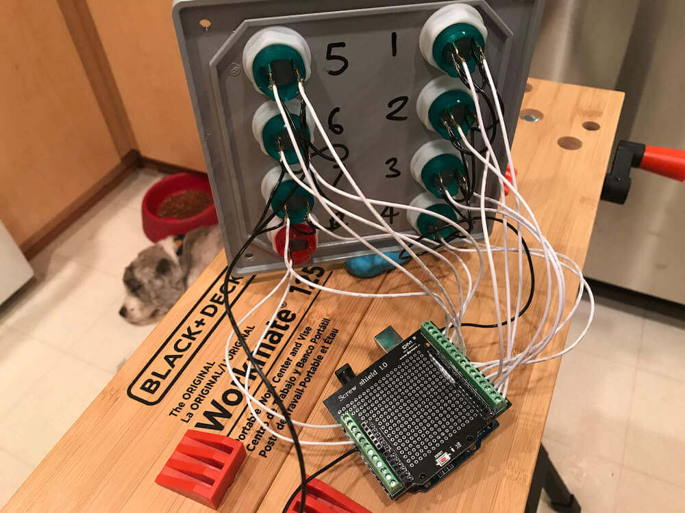
Note the slightly different wiring on the red button: only two wires are connected — the button press terminal and its associated ground. These go to the reset pin and a ground pin on the Arduino. Pressing the button completes a circuit that will immediately reboot the Arduino.
I screwed the flush fit barrel jack power mount into place and soldered the wires from the barrel jack extension cable to it (center = positive for the Arduino). This provided a clean looking power plug from the outside of the box:
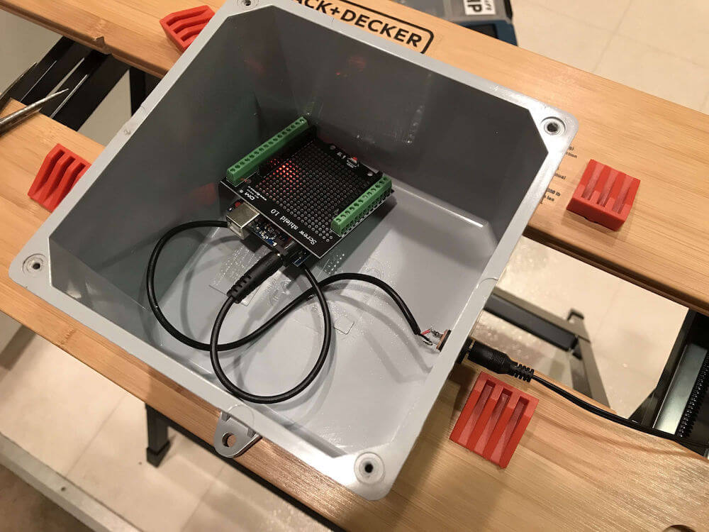
Finally, I carefully put the lid back on the junction box with everything connected to the screw shield. I didn’t dare screw it shut yet as I needed access to plug the USB cable into the Arduino for code downloads and also in case any of the wiring wasn’t working (thankfully the wiring worked first time and I didn’t have to get the soldering iron back out!).
Software
Arduino programming is done in C which may appear a little daunting at first, but doesn’t have to be. You go a long way without ever having to worry about pointers and memory management which can be difficult concepts to grasp at first.
I wrote the code for the task tracker using the Arduino IDE which is a great tool for writing, debugging and installing code on Arduino boards. It’s also provided free of charge and has a nice interface for discovering library code that’s already been written and tested ready for inclusion in your project.
An Arduino program is commonly referred to as a “sketch”. Each sketch should provide implementations for two C functions as follows:
void setup() {
  // Code that gets run once at initial power up...
}

void loop() {
  // Code that gets run continuously while
  // the board is powered on.
}
Most of the code for the task tracker will live in those functions, but I also defined a couple of my own:
void setAllLights(bool turnOn) {
  // Turn all the LEDs on (turnOn === true)
  // or off (turnOn === false)
}

void success() {
  // Do something special once all tasks
  // are completed!
}
Before worrying about the implementation of those, let’s look at the things we need to accomplish at a high level:
- Maintain a true/false (completed / not completed) task status for each of the seven days of the week.
- On power up, turn off all the LEDs and set every task’s status to false for not yet completed.
- Listen for button presses for any of the seven green buttons.
- When a button press is detected, turn on the LED for that button and set that day’s task status to true (completed). If the task was already completed and the LED was on, turn it off and mark the task as incomplete again.
- If all seven task statuses are completed (true) stop listening for any more button press events, give the user some “well done” feedback and don’t allow them to change the task button statuses any more.
- If the red reset button is pressed, reboot to the power on state.
Listening for Button Presses
Detecting a button being pressed should be as simple as reading the value of the digital input pin that the button is connected to, and saying that the button was pressed when this value changes from its previous value. This strategy can be unreliable however as buttons can be held down or generate false positive results from time to time or as they are being pressed or released. To handle such issues, we need to “debounce” the buttons essentially by sampling the value a couple of times within a time period and making sure it stays the same before saying that the button was pressed or released.
Rather than trying to invent a wheel, I found an off the shelf button debouncing library for Arduino called Bounce 2. This provides a simple, battle tested way of reading buttons which allowed me to get on with building a task tracker and not dealing with lower level complications.
Once the library’s added to the project via the Arduino IDE, I was able to use it like so:
#include <Bounce2.h>

// First arcade button is on digital pin 0
#define BUTTON_1 0

// Repeat #define for all seven buttons...
Bounce debouncer1 = Bounce();

// Associate debouncer1 with first arcade button
// using pullup mode
debouncer1.attach(BUTTON_1, INPUT_PULLUP);

// Don't allow another press of this button
// to be detected for 30 milliseconds
debouncer1.interval(30);

// Repeat for all seven buttons...
The attach function associates a debouncer with a specific digital pin on the Arduino, and tells it to use the pullup resistor fuctionality to steer the pin’s value towards the high state when nothing is happening. This eliminates the potential for fluctuations and makes reading the pin state more reliable. For more information on this, check out the Digital Pins page in the Arduino documentation.
Detecting a button press in the loop function looks like this:
debouncer1.update();

// Repeat for all seven buttons...
if (debouncer1.fell()) {
  // Button 1 was pressed, take some action...
}

// Repeat for all seven buttons...
Calling the update function on the debouncer causes it to re-read the associated pin state (Bounce 2 doesn’t use interrupts). The fell function returns true if the signal on the pin had changed from high to low (because the button was pressed). That’s all we need to do to reliably read the button state without getting the false positive and multiple detections of a button press that may otherwise occur without handling debouncing.
You can read more about debouncing here on Wikipedia, or in the context of Arduino programming here in the documentation. The Bounce 2 documentation also contains a good discussion of the problem and techniques that the library uses to mitigate it.
Tracking Task Completion
In order to keep the code nice and simple, I opted to use a global boolean variable for each of the seven tasks… These get initialized to false and then updated when a button is pressed:
bool task1 = false;
bool task2 = false;
bool task3 = false;
...
bool completed = false;
I also added an extra variable completed whose value will be set to true when all seven “task” booleans are true. That will be used to disable further button presses once all the tasks are marked complete.
Recording task completion (or a change of mind that marks a previously completed task as no longer complete) is then as simple as reversing the boolean value of the appropriate variable when handling a button press:
if (debouncer1.fell()) {
  task1 = !task1;
  // TODO: Turn on LED if task1 === true
  // TODO: Turn off LED if task1 === false
}
...
// Similar for the other six buttons / LEDs.
At the end of the loop function I then need to check if all of the tasks have been completed and if so trigger my custom success function after a short delay:
if (task1 && task2 && task3 && task4 && task5 && task6 && task7) {
  isCompleted = true;
  delay(2000);
  success();
}
As I wanted to “freeze” the buttons once all the tasks were completed, I wrapped everything inside the loop function:
if (! completed) {
  // Check for button presses, update LEDs, task status etc...
  // Check if all tasks are complete, set completed true if so.
}
This means that once all the tasks are completed, the code is no longer listening for button presses and the LEDs will stay on until the project is reset for the next week’s task tracking.
Controlling the LEDs
The LEDs mounted in the buttons operate in the same way as “normal” LEDs — that’s to say they appear to the Arduino developer as outputs each individually controllable by their own numbered digital pin. For convenience, I took the pin numbers noted during the assembly phase and gave them more meaningful names in the code:
#define LED_1 1
#define LED_2 3
#define LED_3 5
...
In setup each pin needs to be set as an output:
void setup() {
  pinMode(LED_1, OUTPUT);
  pinMode(LED_2, OUTPUT);
  pinMode(LED_3, OUTPUT);
  ...
}
They can then be turned on and off individually as needed using the Arduino digitalWrite function. Here’s some example code from the setAllLights utility function that’s used a to set all LEDs to the same state:
void setAllLights(bool turnOn) {
  unsigned int ledState = (turnOn ? HIGH : LOW);
  digitalWrite(LED_1, ledState);
  digitalWrite(LED_2, ledState);
  digitalWrite(LED_3, ledState);
  ...
}
When handling a button press, setting the LED to be on when the task has been completed and off when not is then as simple as:
if (debouncer1.fell()) {
  task1 = !task1;
  digitalWrite(LED_1, task1 ? HIGH : LOW);
}
...
// Similar for the other six buttons / LEDs.
Celebrating Success
Once all the tasks are completed, the code invokes the success function — I wanted this to give the user some sort of visual reward as payoff for achieving their weekly goals. I decided on a sort of snake like effect with the LEDs as shown below:
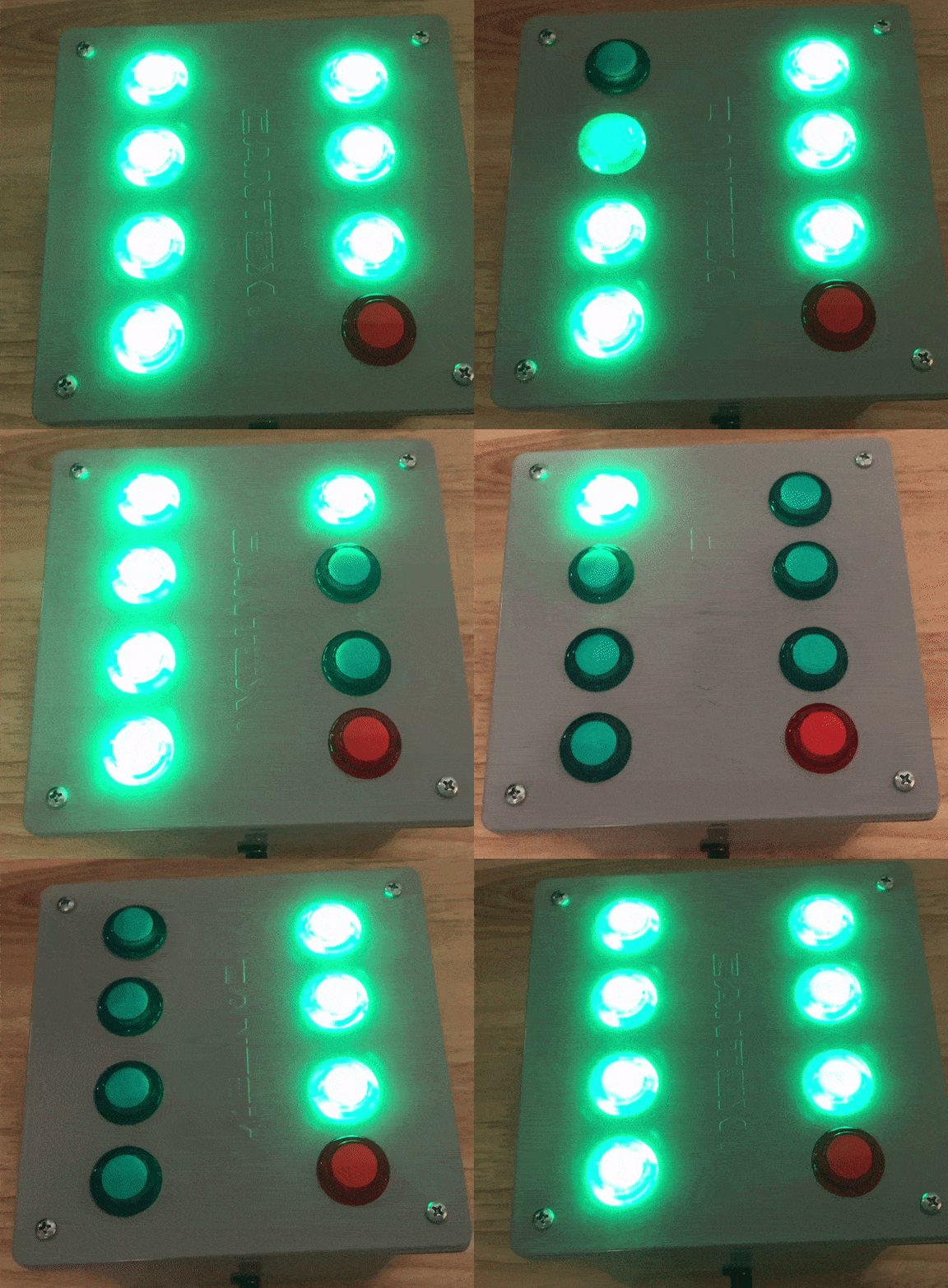
Implementing this was pretty straightforward… turn off all the lights using my other setAllLights function, loop a few times and every other time turn each light on or off with a short delay. Then turn them all back on again:
void success() {
  setAllLights(false);
  for (unsigned int n = 0; n < 6; n++) {
    unsigned int ledState = (n % 2 == 0 ? HIGH : LOW);
    digitalWrite(LED_1, ledState);
    delay(200);
    digitalWrite(LED_2, ledState);
    delay(200);
    ...
    // Repeat for all seven LEDs...
  }
  setAllLights(true);
}
Resetting for Another Week
As the red button is wired to the Arduino’s hardware reset circuit, pressing it will restart the Arduino as if the power had been cycled. This clears out everything in RAM, re-initializes global variables and runs the setup function again. The code is then back in the start state for another week. Therefore there’s no code required to reset at the end of the week, everything is handled by hardware.
If you want to see the complete source code, check out my repo on GitHub.
Shopping List
If you want to try building one of these for yourself or your own kids, here’s a list of everything I used in the build…
Tools
- Power drill: cuts through PVC like butter, but use eye protection when doing so.
- Forstner drill bits (12mm diameter for the power jack and 25mm for the arcade buttons — you don’t have to be too precise as the buttons and power jack have flange like fittings so will cover a slightly larger hole): makes drilling circular holes a breeze. I got mine from Harbor Freight who sell a set containing both sizes that I needed.
- Phillips screwdriver: for opening and sealing the junction box.
- Jeweler’s screwdriver set: used to operate the tiny screws on the Arduino screw shield (get a set here). Only needed if you’re using the screw shield.
- Pliers: for tightening the power barrel jack and generally holding stuff.
- Soldering iron and solder: for attaching the ground wires, or all wires if you choose to go the full solder route rather than using the screw shield and arcade button quick connect wires.
Hardware
- Arduino Uno or compatible equivalent.
- Arduino screw shield (optional: saves a lot of soldering, but if you’re good at that you probably don’t need it and can simply solder the wires direct to the Arduino pins).
- USB A-B data cable for Arduino Uno (to download code to the board). You only need this when programming the board, you may already have one connecting your printer to your computer?
- Barrel jack power supply (12v, 1A).
- Panel mount barrel jack for power supply (to flush mount the power plug into the junction box).
- Barrel jack extension cable (to connect the panel mount barrel jack to the Arduino power supply).
- 6”x6”x4” PVC electrical junction box.
- 7 green 24mm LED arcade buttons.
- 1 red 24mm LED arcade button.
- Solid core 22AWG wire for ground connections (solid core is much easier for soldering than stranded wire). Any old speaker type wire should do.
- 1 pack of Arcade button quick connect wires (optional: saves a lot of extra soldering but if you’re good at that you can just use more 22AWG solid core wire instead).
Software
All of the required software is free and can be downloaded directly:
- Arduino IDE (for writing, testing, downloading code). This is available for Windows, MacOS and Linux. There’s also a version that runs in the browser, but I’ve no experience with that.
- Bounce 2 debounce library for Arduino: saves re-inventing wheels. Can be installed directly from the Arduino IDE (Sketch -> Include Library -> Manage Libraries).
- If you want to use my code for the task tracker application, it’s freely available on my GitHub for you to re-use or modify as you see fit. If you do use it, I’d love to see what you make!
It turns out that my initial project video was pretty popular, and got picked up by the official Arduino Twitter feed:
Inspired by @SimoneGiertz's Every Day Calendar, @simon_prickett designed a weekly task tracker for his son using Arduino and LED arcade buttons: https://t.co/fAX0mARzkk pic.twitter.com/q9jVU56PMZ
— Arduino (@arduino) December 11, 2018
Hopefully this has inspired you to try something similar — if you have a go, let me know what you get up to! I’m going to build a four button version next using green, red, yellow and blue LEDs to see if I can re-imagine the classic Simon memory game…
 Simon Prickett
 Building a Smart Card Transit Ticketing System with Redis and Raspberry Pi