 Simon Prickett
Flip dot displays were a popular way of displaying destination information on buses and other forms of public transport. A flip dot sign is a matrix of individual dots, each having a brightly coloured and a dark side. Each dot can be controlled individually using magnets - when the state changes, the dot flips sides and makes a very satisfying sound. I bought an old flip dot display that had been used in a bus and worked with existing software drivers for it to make it a fun display piece for my office and livestreaming setup.
The Raspberry Pint Meetup Group invited me to talk about how flip dot displays work at one of their hybrid meetup events. I’ve embeeded the video of my talk below - this article is a transcript of the talk with images of the slide deck throughout and a list of resources at the end. Enjoy!
Your support helps to fund future projects!
Annotated Video Transcript
This talk is about flip dots and managing a flip dot display with a Raspberry Pi. Before we go any further what we can do is take a look at the thing behind me - it is a flip dot display. For scale, there’s a Raspberry Pi 4 in a box - so it’s quite big. It’s also extremely heavy, because each one of these dots it electromechanical. It’s not using LEDs. It weighs quite a lot, it’s difficult to bring to London and navigate the tube, so it’s staying up here in Nottingham and we’re doing this remotely.
What does it do? Let’s see if we can make it do something…
It basically does anything you want - they are usually, or were, used in digital signage. They make a lovely noise when they change and the other thing that they’ve got going for them is that when they’re not changing they don’t really consume any power. There’s no lights involved here, these are very bright on one side and black on the other and it’s all done with electromagnets.
Before we play around with this some more, we need to go look at “What are these things and where do they come from?”.
To answer this, we need to talk about buses a little bit because this thing behind me came out of a bus. Around the year 2000 it was fitted into a bus… that bus was later scrapped, I’m not sure when. It was parted out and I was able to buy the sign. The purpose of these signs is that they generally serve as destination blinds in buses. They tell you where the bus is going to go, or what the next stop is or whatever.
They were popular for a while because they have a couple of properties we’ll look at in a minute, but historically these were just blinds…
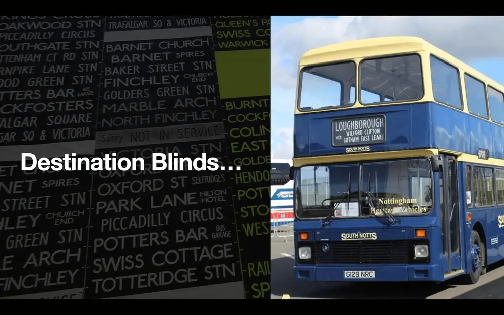
They were just bits of fabric with the destinations written on, and the driver would wind a handle and around would come the next destination. There’s a few buses in this presentation - they’re all Nottingham-based ones which is where I grew up. The one above is one that used to take me to school.
Buses that you see these days don’t have flip dot displays….
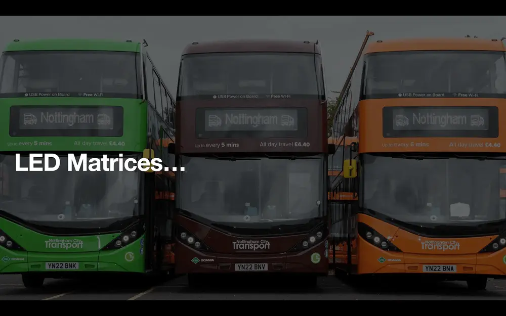
What you see on buses now is LED matrices which are essentially like the sort of things you can buy in maker kits - they have LEDS which are usually a single colour. In vehicles they have this high visibility property and unlike flip dots they are silent and do require constant power (albeit very low power these days). Modern buses all use LEDs.
Somewhere in between destination blinds and LEDs we had a period where things were a bit cooler… and we had what was called a split flap display:
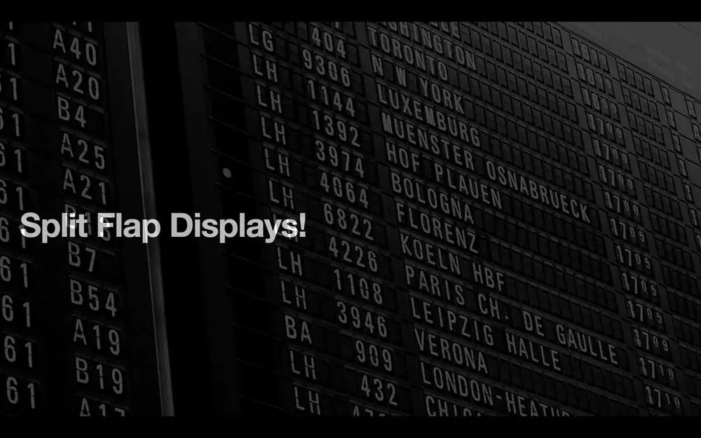
You might have seen these in Waterloo Station sometime ago although they’re long gone now. Frankfurt Airport still has them. They’re those displays where, when something changes, it makes this amazing clacking sound and the letters all spin around and then is settles down to the new state. These are really cool - you can make them, you can also buy them from certain maker companies too. However, they’re really expensive because each letter has got the whole alphabet in there plus all of the numbers then some punctuation and anything else you wanted to put on the screen.
Split flap displays were kind of fun and expensive, and also had the property of no power consumption when they aren’t updating. Inbetween split flap displays and LEDs there were these flip dot things that had their day.

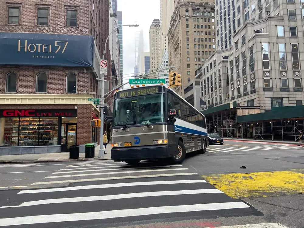
This was the hardest picture to source for this whole presentation. “Can I find a picture of the flip dot display installed in a bus?” The answer is generally “no” because they seem to have existed for a moment in time and then stopped. You might also have seen flip dots in use as clocks on railway platforms. The bus we’re looking at here is in New York - it’s using a flip dot display with a back light. My sign here also has a backlight but you don’t really need it unless it’s very dark outside because the dots themselves are so bright.
As happened to the bus that my sign came from, a lot of these buses got retired and broken up. The flip dot signs from them are having a second life in the maker community for a couple of reasons:
One because they have this really satisfying mechanical property: they make noise when they change. So you don’t need to annouce that something’s about to change, you just change it and it makes a clack clack noise as the sign updates as we’ve already seen and will see some more of later.
The other reason is because the company that made them put out a relatively decent amount of information about them and did so in PDF files, so people have reverse engineered how to operate these and how to wire them up.
They are fairly simple - it takes 24 Volt power (as provided in a vehicle) and that’s about all. We’ll look at the data protocol in a minute.
So flip dot signs are having a bit of a second life. In the big scheme of things, these signs are not that expensive as they are mostly from scrapped buses. There are places to buy “new old stock” signs that were never fitted to a bus in the first place - they’re just very old and have been sat on a shelf.
How does the sign work?
Watch the loop for a moment - it’s been slowed down quite a lot. What happens is that each dot in the sign, or the matrix, has a very very bright side and a very very dark side. Each dot is on a hinge or pole at the top and bottom and there’s electromagnets / a solenoid in each one. To control these, you tell each one to turn on or off and it changes the magnets around causing the dot to flip which is why you have this noise… it is actually turning and banging into the other side when it finishes.
This is also why it’s “object permanent” if you like. You can turn it off and it will stay where it was. You could turn it upside down, ship it to someone else using UPS or whatever and it’s still going to be in the same state.
That’s how it works, and this is a blown up diagram that I made of what they look like:

Each one is just this two coloured thing and it sits on a rod and behind there there’s a couple of electromagnets. But, there’s lots and lots of these mechanisms. This particular sign I’ve got is the medium sized sign - it’s the one that would go down the side of the bus, not on the front or the back. These signs generally work in threes: there’s a front one which is really big, a side one which is that big (points to sign behind him) and a rear one that might just have space to display a route number. Later, we’ll look at how the protocol works if you have multiple signs connected together.
Basically, the sign presents to the programmer as a giant bit array:
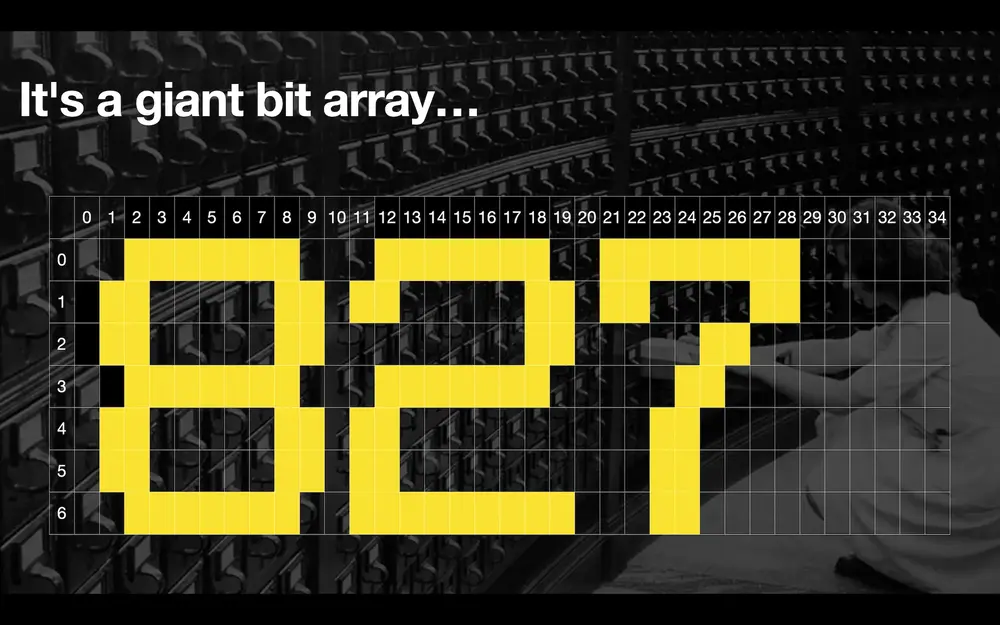
I’ve got a 7 x 87 (oops - it’s actually 84!) sign, so that’s 0 to 6 and then 0 to 86 (correction: 83) across the width. The sign has no concept of text, or fonts, or anything really… it’s just on or off for each dot. Anything you want to draw on there requires you to figure out yourself.
Like Mark (the previous speaker on the night) was saying earlier, a lot of us grew up with early ZX Spectrums - you use to have graph paper from WH Smith and you’d draw 8x8 pixel sprites for your game or whatever you were making. These signs use that same bitmap array approach.
So how do we control the thing?
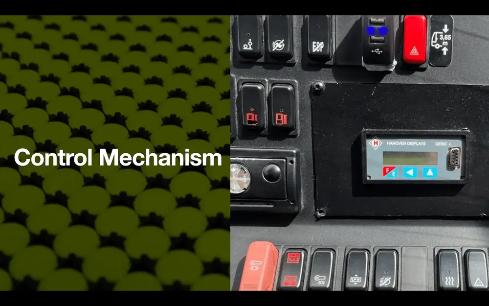
We’ve got this sign, it’s originally from a bus… it’s not designed for use with any sort of programming language really. When the sign was installed in the bus originally you’d also buy that little unit on the right there, which is a controller unit for it. You would plug a laptop into the serial port on there and use proprietary software to load a set of destinations. You’d then use the buttons on the controller to flip through available destinations and send them to the sign. It then sends the data to signs at the front, side and back of the bus.
This would give the bus driver a pre-programmed set of approved destination messages, which is probably what you want… again going back to Mark’s (previous speaker) example of how we all walked into Currys or WH Smiths or Woolworth or whatever and did 10 PRINT <something rude> 20 GOTO 10 on the old BASIC computers from the 80s… you don’t want to give the driver free text input to put any old thing they want on the front of the bus and then go driving it around on their last day at work! That would not be good for anybody.
The actual controller was quite limited in what it could do and required proprietary programming via a laptop.
People who are better than me at electronics looked at this and started looking at how the controller talks to the sign (all credit to John Whittington for writing an excellent article about this). Similarly to parts of Mark’s (the previous speaker) project, it uses RS-485 which is a pretty simple way of connecting A to B. This means that we can connect the sign to lots of different computers. You can get a USB to RS485 modem type thing for about £3-4 on Amazon, eBay etc. You can treat that in your code as a sort of USB modem and send it whatever protocol the thing at the other end is expecting. The thing at the other end will then react to that.
The bus sign protocol for controlling the signs is really quite strange:
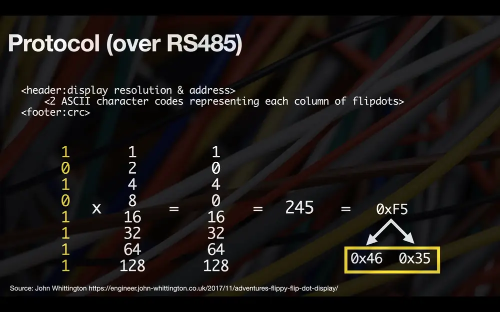
Imagine if we had 8 dots in a column and we wanted to turn on the 1st, 3rd, 5th, 6th, 7th and 8th dots. You could look at them like this:
This one here (the top most one) represents the top left flip dot and it should be on (yellow side out). The zero below represents the flip dot below it and that needs to be off (black side out).
The way the protocol works is that there’s first a header “hey this is for a bus sign”. Then we send an address - that’s because there’s potentially up to three signs in a vehicle, they’re all wired together. Each has a different wiring bus address (1, 2, 3…) which is set using a switch on the back of the sign. The sign then only listens to messages for that address.
Then we need to encode every single column, in my case I have 87 of them (correction: 84). We do it like this which is a little bit weird but luckily other people got there first and figured this out!
What we do is treat this as a binary number… the first 1 is worth 1, and the 0 is 2, the next 1 is worth 4 and so on. We should then have a column of numbers with the more significant numbers as we go down… add them all together to give a total… we get 245, which is decimal representation of this column of flip dots here.
Where this protocol is really strange is that it requires us to turn that 245 into a hex number 0xF5. You’d think that’s maybe the end of it but what the protocol actually wants is the ASCII codes for each of those hex digits.. 0x46 and 0x35.
So to encode that column of flip dots to send to the sign you need to do the maths to do all of this and you come out with 0x46 0x35. Having done the same for each column, you’d then get all of the values together, calculate a CRC (cyclic reudundancy check) code to make sure that the sign can determine that it’s received all of the data without corruption.
All of this data is sent across the USB/RS485 modem and the sign updates. What is important to note here is that it’s a broadcast. It’s like TV or pub/sub if you’re familiar with publish/subscribe protocols. You just put it out there on the RS485 and the sign either updates or it doesn’t… if it wasn’t listening because it’s on the wrong address then it’s not going to update. If the data’s corrupt it’s not going to update. It’s not going to tell you when it’s finished updating either, so you have to time these things a bit as it takes a finite amount of time for the sign to update… there’s only so many frames you can send in a second.
It’s essentially a one frame per communication type of broadcast TV thing. Luckily, most people won’t need to worry about this because people went ahead and wrote drivers for these signs which make them a lot more accessible to those just wanting to get on with doing projects…
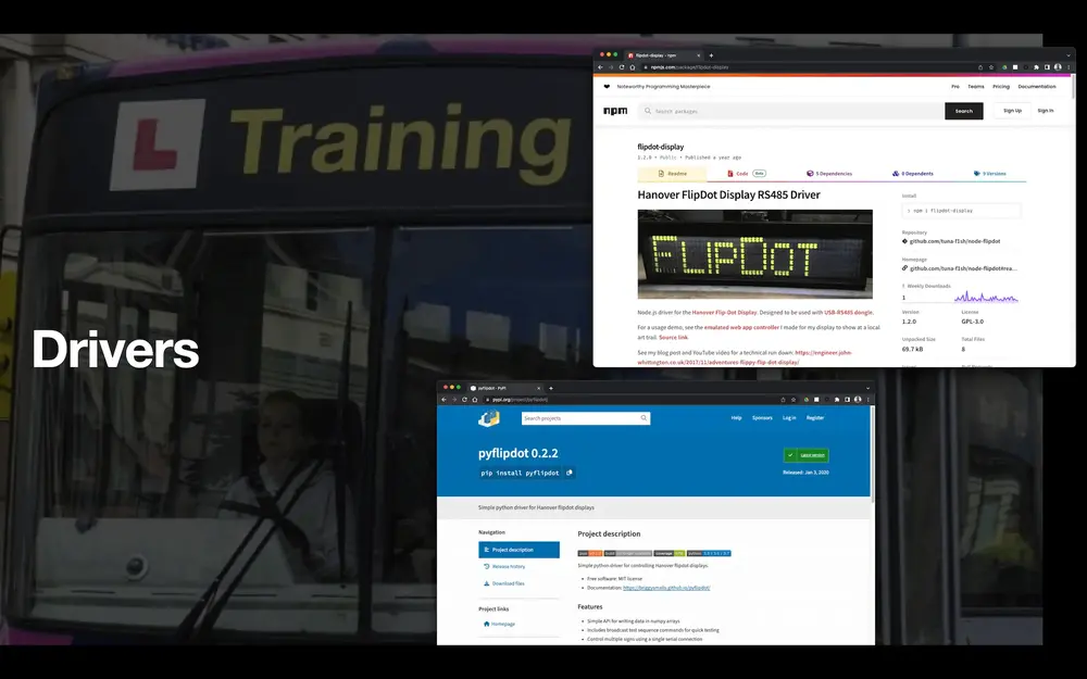
I’ve mostly worked with the Node.js driver in the top right. It’s probably the most mature one. It supports fonts so you can send it text and the driver works out all of the ASCII font stuff that you need to represent letters. This is what we were using in the demo earlier. It also supports scrolling - send a message that’s bigger than your sign is wide and it will scroll it across the sign for you. It also has a debug mode where you can see what’s going on with the protocol underneath - handy if you wanted to do something a bit trickier.
Again - what you have to do when working with these signs is remember that every update sets every flip dot even if it’s not changed. There isn’t a delta mechanism - you can’t say “I know I turned them all on, now we’re going to starting turning some of these off”. It literally is like making a flip book - you have to keep sending it the whole frame, you can’t send it just deltas.
There’s also a Python interface which works more in the model of the sign being a big array / buffer. You send it a big array of “on / off / on / off / off / on / off etc” and it encodes it for you and sends it to the sign. If you want to work with this one and fonts, you’re going to have to figure out the encoding of those fonts yourself so you’re back to the ZX Spectrum days with the graph paper and figuring out what your sprite looks like.
Those are the main two drivers that are out there. You can of course write your own because we know what the protocol is. At some point I might want to try this with the little Raspberry Pi Pico W and see if we can do it in MicroPython, but for now these two work great.
What does any of this have to do with Raspberry Pi? Well - anything and nothing really as we are plugging a USB/RS485 in… the main advantages of using a Raspberry Pi here are that it’s got a USB port… but so do most things… I could plug this into my Macintosh. The Pi can however also be mounted in the back of the sign. I’ve got a Pi 3 stuck in the back of the sign here with some stick on velcro from B&Q:
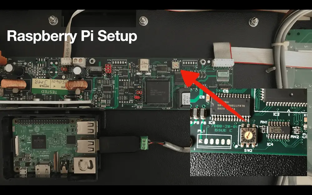
That’s the RS485 down there, the thing with the green screw blocks and a couple of wires. The expanded view there is my address selector. I’ve got bus address 1 selected in this example, so when we address this sign we’d know it as sign number 1. If we had multiple signs chained together like in a real bus we could send messages to each, or the same message to all of them at the same time (note: this would require all the signs to be the same size).
How does it work in code? There’s two ways of coding for the sign using the drivers provided. This is a Node.js example:
It doesn’t necessarily lend itself particularly well to Node.js because Node is asynchronous and non-blocking and this is pretty much the opposite of that. What we need to do is form up the message that we want to send to the sign. We do that with a writeText function in the driver here. It handles encoding the font into the protocol for us.
What we do then is send it to the sign. But, sending it to the sign is a broadcast: there’s no way that I know that the sign has done the thing. Inside this Node program I can register for a “the driver has finished sending the data” event, but that doesn’t tell me if the sign has received it and finished updating itself yet. There’s a lot of playing the sleep/wait game here which is not very Node-centric. This is why you see a lot of Promises there that involve sleeping for a bit and setting timeouts.
If we want to display a long message on this sign as multiple words, we have to “write something then sleep, write something then sleep”. We’re not going to get told “OK the sign updated, you can move to the next word(s)”.
In Python the interface is slightly different: they took a different approach and what we here is that again it presents as a serial modem. In this case we tell it how big the sign is - I’ve got address 6, sign size 84 x 7 configured:
Then what we do is create an image inside the driver. This is just a big array of bytes. We plot into it as if it was a bitmap. I’ve got random x,y co-ordinates generated here then I’m just setting the bit in that position to True or False for on or off. It’s a much lower level driver.
This is not as great for text, but it’s really good for writing games or something like that. If you want to do something else with one of these, we’ll also take a look at examples of what you can do…

What’s a practical application of one of these displays? Really there isn’t one, it’s kind of just for fun. I took something that I would have been doing anyway and which also involves a lot of other Raspberry Pi stuff and I started doing aircraft tracking with the display I have here. Let’s look at a very complicated diagram:
As part of my day to day job, I do Developer Advocacy for a database company so I get to build projects with databases and Raspberry Pis. I started looking at ADS-B receivers, which are a bit of hardware that you can buy that plugs into a computer and it receives messages from passing aircraft (I forgot to mention you also need an aerial for this).
I started looking at what we could do with that information - I started putting it into a database, and then taking the basic information that you get about the aircraft: callsign, height, latitude, longitude and using it to look up where the aircraft is coming from, where it’s going to, what sort of aircraft is it and who owns it… getting this information from the FlightAware API (note: this is a paid service).
I built a whole project with that and the sign is a front end for that. This is where the sign having mechanical movement is really useful because, if nothing’s going on out there in East Midlands Aiport land, nothing’s passing over us here in Nottingham then it’s quiet, but when something happens the sign just by virtue of updating makes quite a racket and you can hear it and know to look around at it because something is happening.
In this project, which is a whole other thing - it’s a lengthy talk or a set of livestream videos that are on my website (here) if you want to see how that works - the sign is a front end. I can show that working…
The other fun thing here, I am SSH’ed into bussign.local on my network because there’s a Pi in there - I’m SSH’ed into the bus sign and I can run stuff on it. Let’s run the front end of the plane tracking project (full article on this project)…
This depends on live flight traffic that my aerial can see but hopefully at some point the sign will have an update and what happens when that occurs – here it goes!
It’s a Ryanair flight from Dublin to somewhere on a 737 that’s passing by. If we get any new information from that plane, for example if it changes altitude it will display the update on the sign. Here it goes again - Dublin to Luton this time so we’ve picked up another flight, a 737-800. There’s the registration, here’s the altitude and so on.
I have it repeating the information a couple of times so that if the first time the sound catches your attention and you miss something you can just keep watching it. This is how these things work in public displays: you might have seen them on platforms in railway stations being used as a clock - you can here when it ticks over to a new minute, or providing train arrival/departure information. We’ve picked up another plane - Manchester to Heathrow on a BA A320.
This is an example of using the sign with real time stuff. There are other components to this system that aren’t in the back of the sign but they all could be - they could all run on that one Pi. I’ve actually got a component that’s listening to the radio and putting things into the database running somewhere else in the room, but it doesn’t have to be separate.
If we stop the code, the sign’s state is frozen - the sign doesn’t do anything when it’s not being updated.
That’s an example of using it for a real project. The other sort of thing that we can use it for is fun - I’m currently working on Flappy Bird (but very slow) for it.
At the minute as you can see, there’s no moving of the bird but the collision detection is there: when the bird hits the bar there, everything stops and the scoring stops.
How fast can you make one of these things update? It’s a function of how many flip dots you have because the sign updates from the left side to the right, which is why you see thinks janking across the screen there and they are slightly out of sync. The wider your sign is, the slower the update. My sign can be reliably driven from Python at about two updates per second - the game can’t really get any faster than this and would start skipping frames if we did that.
We can build games and all sorts out of these. The game is also shown later in the day so I had the backlight on in this case. You don’t control the backlight through software, there’s just a button on the top that I put in there. It would have been connected to the vehicle’s headlight circuit originally.
Other people have been doing stuff with these as well. They seem to be having a bit of a renaissance. The Pimoroni folks saw this one on my live stream and they’ve bought one:
A rare instance of a maker being a bad influence on *us*.
— pimoroni (@pimoroni) April 14, 2023
Bravo @simon_prickett. Enabler of flipdots! pic.twitter.com/Y5HaMUWnwo
Somebody else in Telford saw mine, and they’ve bought one and replicated the whole plane tracking project and are doing other things with it:
I was mad enough to copy 😄
— Jake Turner (@jaket91) April 7, 2023
Thanks for the awesome intro’s to nodejs and redis too! I do want to rewrite some of the components in Python, mainly because of familiarity.
I noticed the address was 1 out using the js but matched the potentiometer in Python - did you have the same? pic.twitter.com/syOVhJB2wA
You might have seen this guy - he’s called Sam Battle, he’s known as “Look Mum No Computer”. He does synthesizer stuff and he also does electronics projects. He built one of these for a makers giveaway at Christmas - it’s a sort of etch a sketch:
The video’s sped up a little but with these smaller versions of the sign you can do faster updates because there’s just less stuff going down the bus and it takes less time to ripple it across the screen.
There’s no reason why we can’t do something more interesting with the Pi in the back of the sign because everything to do with the sign connects to a single USB port. All of the GPIO pins are still free, so I can put an arcade button on there or a joystick or a trackballl or something and build whatever you can think of that fits into the display area.
The other thing that I wanted to show quickly was that these things get out and about elsewhere…
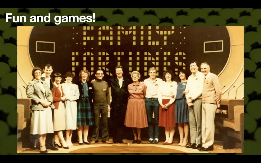
I couldn’t quite find the right picture but Italian Family Fortunes used a flip dot display for years and apparently the British one did for a little while. They definitely were a thing for a while.
The company that made mine is called Hanover Displays - they’re still around but they make other things now… you’re not going to get a new one of these. But if you are interested, and you do want to get hold of one then the usual place is probably eBay.
Like with anything else, stuff crops up on eBay from time to time. I know from experience that if you buy a large component of a bus on eBay then eBay will continue to try and sell you the rest of the bus - my eBay recommendations are now double decker buses etc. Mine did come from a bus scrapyard on eBay that assured me it was working. There was one out in Wales when I looked on there last week.
There’s also a company PSV Automobilia dot com. I don’t know anything about them other than a couple of people have bought signs from them and said they’ve been great.
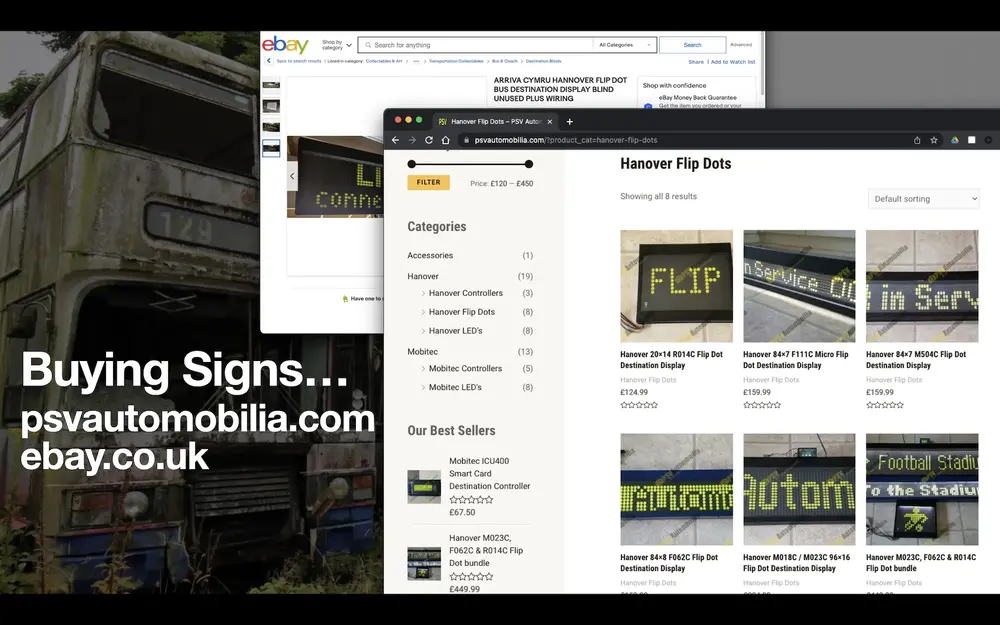
PSV Automobilia have new old stock signs, and have all of the sizes. They do packages too.
How much do they cost? Mine cost me I think £112 shipped - they are heavy, so it’ll be using Parcelforce or UPS. One from PSV will cost a little bit more because it’s likely to be a bit cleaner and have a guaranteed power source.
What else do you need to make it work? I’m using a laptop power supply that puts out 20v, it turns out that’s pretty adequate. I’m using 20v 5A because 20v 1A either powered the backlight or the flip discs, so the sign would work until I turned the backlight on then it would stop. It can take up to 24v which is possibly an easier way to go.
The other thing that’s cool, like these displays, and maybe the future is something called a mechanical seven segment display.
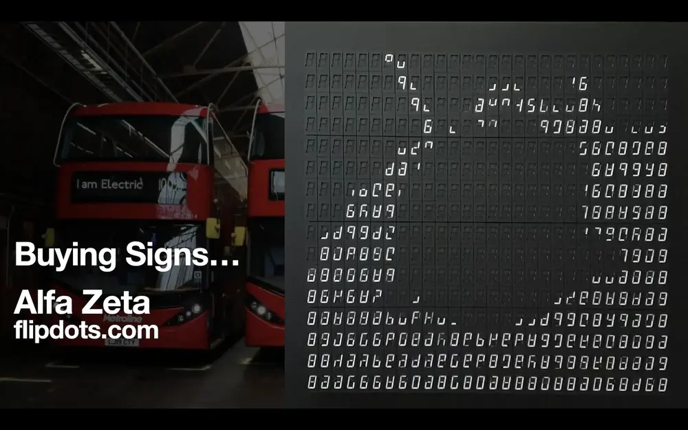
You might have seen seven segment displays in old calculators, they’re always a popular maker project. Four digit ones are cheap to buy, you can plug them into a load of GPIOs and control each segment.
What this is is - imagine that combined with the flip dot. Each of these seven segments is itself a tiny little mechanical thing that makes that really nice noise when it moves. Instead of having on/off in one pixel, you can have any combination of the seven segments on or off times the size of the board. These are brand new and manufactured today and the speed of them is significantly higher. There are people out there doing really nice projects with things like the time of flight sensor that Mark (the previous speaker) mentioned. You put your hand in front of it and it draws the outline of your hand in one of these displays. As you move around it makes a really satisfying sound.
I have no idea how much those cost, they’re not something that I (currently) have access to.
That’s really the end of the talk, so if you want to learn more about this here’s some resources(see below). Thanks everybody!
Resources
- Flip Dot Display Node.js driver
- Flip Dot Display Python driver
- Article by John Whittington, author of the Node.js driver
- My aircraft tracking project that uses the flip dot sign
- Look Mum No Computer’s flip dot etch-a-sketch video
- PSV Automobilia - a seller of flip dot displays
- USB to RS485 adapter
Main photograph by MTATransitFan at WikiMedia Commons.
 Taking Pictures with Raspberry Pi and Redis